MANUAL TRANSMISSION SYSTEM, Diagnostic DTC:P0717, P0806, P0811
| DTC Code | DTC Name |
|---|---|
| P0717 | Input/Turbine Speed Sensor "A" Circuit No Signal |
| P0806 | Clutch Position Sensor Circuit Range/Performance |
| P0811 | Excessive Clutch Slippage |
DESCRIPTION
| DTC No. | Detection Item | DTC Detection Condition | Trouble Area | Warning Indicate | Memory |
|---|---|---|---|---|---|
| P0717 | Input/Turbine Speed Sensor "A" Circuit No Signal | While driving after warm-up with clutch engaged, transmission input speed is not input (1-trip detection logic) |
|
Master Warning Light: Comes on |
DTC stored |
| P0806 | Clutch Position Sensor Circuit Range/Performance | While driving after warm-up with clutch engaged, clutch stroke sensor value continuously indicates clutch disengaged (1-trip detection logic) |
|
Master Warning Light: Comes on |
DTC stored |
| P0811 | Excessive Clutch Slippage | With clutch completely engaged, divergence between transmission input speed and engine speed is continuously greater than threshold (1-trip detection logic) |
|
Master Warning Light: Comes on |
DTC stored |
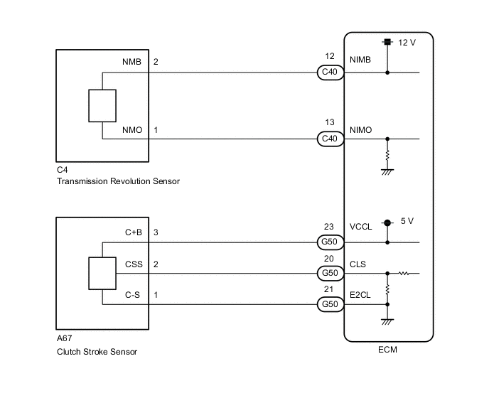
WIRING DIAGRAM
CAUTION / NOTICE / HINT
Note
Perform registration and/or initialization when parts related to the iMT system are replaced.
Tech Tips
After the repair, clear the DTCs and perform the following procedure to check that DTCs are not output.
-
Perform the Road Test.
-
Check for DTCs again.
PROCEDURE
-
READ VALUE USING GTS (ENGINE SPEED AND SPD (NIM))
-
Connect the GTS to the DLC3.
-
Turn the ignition switch to ON.
-
Turn the GTS on.
-
Enter the following menus: Powertrain / Engine and ECT / Data List
-
According to the display on the GTS, read the Data List.
Powertrain > Engine and ECT > Data ListTester Display Measurement Item Range Normal Condition Diagnostic Note Engine Speed Engine speed Min.: 0 rpm
Max.: 16383 rpm
710 to 810 rpm: Idling When the crankshaft position sensor is malfunctioning, "Engine Speed" is approximately 0 rpm or varies greatly from the actual engine speed. SPD (NIM) Input shaft speed (NIM) Min.: 0 rpm
Max.: 16383 rpm
Input shaft speed (NIM) equal to engine speed (NE): Clutch pedal not depressed, vehicle running -
Powertrain > Engine and ECT > Data ListTester Display Engine Speed SPD (NIM) OK When the clutch is engaged, the engine speed is constant and the difference between "Engine Speed" and "SPD (NIM)" in the Data List is below 200 rpm. Result Proceed to OK NG
NG 
CHECK CLUTCH SLIPS Click here
OK 
-
-
READ VALUE USING GTS (CLUTCH STROKE POSITION)
-
Connect the GTS to the DLC3.
-
Turn the ignition switch to ON.
-
Turn the GTS on.
-
Enter the following menus: Powertrain / Engine and ECT / Data List
-
According to the display on the GTS, read the Data List.
Powertrain > Engine and ECT > Data ListTester Display Measurement Item Range Normal Condition Diagnostic Note Clutch Stroke Position Clutch stroke calculated by ECM Min.: -200%
Max.: 199.9%
Value increases: Clutch pedal released → clutch pedal fully depressed -
Powertrain > Engine and ECT > Data ListTester Display Clutch Stroke Position Result Result Proceed to Data display is within Normal Condition range A Data display is not within Normal Condition range B
A 
CHECK FOR INTERMITTENT PROBLEMS Click here
B
-
-
CHECK HARNESS AND CONNECTOR (CLUTCH STROKE SENSOR - ECM)
-
Disconnect the clutch stroke sensor connector.
-
Disconnect the ECM connector.
-
Measure the resistance according to the value(s) in the table below.
Standard Resistance Tester Connection Condition Specified Condition A67-3 (C+B) - G50-23 (VCCL) Always Below 1 Ω A67-2 (CSS) - G50-20 (CLS) Always Below 1 Ω A67-1 (C-S) - G50-21 (E2CL) Always Below 1 Ω A67-3 (C+B) - Body ground Always 10 kΩ or higher A67-2 (CSS) - Body ground Always 10 kΩ or higher A67-1 (C-S) - Body ground Always 10 kΩ or higher Result Proceed to OK NG
NG
REPAIR OR REPLACE HARNESS OR CONNECTOR
OK
-
-
CHECK TERMINAL VOLTAGE (POWER SOURCE OF CLUTCH STROKE SENSOR)
-
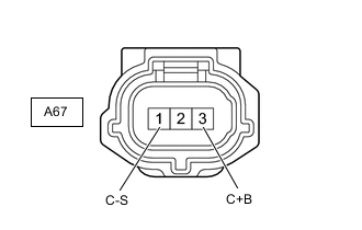
*a Front view of wire harness connector
(to Clutch Stroke Sensor)
Disconnect the clutch stroke sensor connector.
-
Measure the voltage according to the value(s) in the table below.
Standard Voltage Tester Connection Switch Condition Specified Condition A67-3 (C+B) - A67-1 (C-S) Ignition switch ON 4.5 to 5.5 V Result Proceed to OK NG
NG
REPLACE ECM Click here
OK
-
-
INSPECT CLUTCH STROKE SENSOR
-
Inspect the clutch stroke sensor.
Result Proceed to OK NG
OK
REPLACE ECM Click here
NG
REPLACE CLUTCH MASTER CYLINDER ASSEMBLY Click here
-
-
CHECK CLUTCH SLIPS
-
Refer to the "Clutch slips" item in the problem symptoms table for the clutch system and check each part.
OK Inspections of all suspected areas are normal. Result Proceed to OK NG
NG
ADJUST OR REPLACE MALFUNCTIONING PARTS
OK
-
-
INSPECT TRANSMISSION REVOLUTION SENSOR INSTALLATION
-
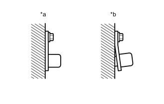
*a CORRECT *b INCORRECT Check the transmission revolution sensor installation.
OK The installation bolt is tightened properly and there is no clearance between the sensor and transmission case. Result Proceed to OK NG
NG
SECURELY INSTALL OR REPLACE TRANSMISSION REVOLUTION SENSOR Click here
OK
-
-
CHECK HARNESS AND CONNECTOR (TRANSMISSION REVOLUTION SENSOR - ECM)
-
Disconnect the transmission revolution sensor connector.
-
Disconnect the ECM connector.
-
Measure the resistance according to the value(s) in the table below.
Standard Resistance Tester Connection Condition Specified Condition C4-2 (NMB) - C40-12 (NIMB) Always Below 1 Ω C4-1 (NMO) - C40-13 (NIMO) Always Below 1 Ω C4-2 (NMB) - Body ground Always 10 kΩ or higher C4-1 (NMO) - Body ground Always 10 kΩ or higher Result Proceed to OK NG
NG
REPAIR OR REPLACE HARNESS OR CONNECTOR
OK
-
-
INSPECT TRANSMISSION REVOLUTION SENSOR
-
Inspect transmission revolution sensor.
Result Proceed to OK NG
NG
REPLACE TRANSMISSION REVOLUTION SENSOR Click here
OK
-
-
INSPECT COUNTER SHAFT (TEETH OF COUNTERSHAFT 2ND SPEED GEAR)
-
Inspect the teeth of the countershaft 2nd speed gear.
OK No tooth damage on countershaft 2nd speed gear. Result Proceed to OK NG
OK
REPLACE ECM Click here
NG
REPLACE COUNTERSHAFT 2ND SPEED GEAR Click here
-