AUTOMATIC TRANSMISSION SYSTEM(for 2GD-FTV), Diagnostic DTC:P2772

| DTC Code | DTC Name |
|---|---|
| P2772 | Four Wheel Drive (4WD) Low Switch Circuit Range / Performance |
DESCRIPTION
The ECM detects the signal from the L4 detection switch.
This DTC indicates that the L4 detection switch remains on.
| DTC No. | Detection Item | DTC Detection Condition | Trouble Area | MIL | Memory |
|---|---|---|---|---|---|
| P2772 | Four Wheel Drive (4WD) Low Switch Circuit Range / Performance | L4 detection switch remains on while the vehicle is being driven under the following conditions for 1.8 seconds or more (1 trip detection logic): (a) Output shaft speed is between 1000 and 3000 rpm. (b) Transfer position switch is in H2 or H4. |
|
Comes on | DTC stored |
MONITOR DESCRIPTION
The ECM monitors the L4 detection switch to determine when the transfer case L4 gears are engaged. If the transfer case L4 gears remain engaged under the following conditions, the ECM will conclude that there is a malfunction of the L4 detection switch, illuminate the MIL and store the DTC:
-
The L4 detection switch indicates that the L4 transfer case gears are engaged.
-
The transfer position switch is in H2 or H4.
-
The transfer case output shaft speed is between 1000 and 3000 rpm.
-
The specified time period has elapsed.
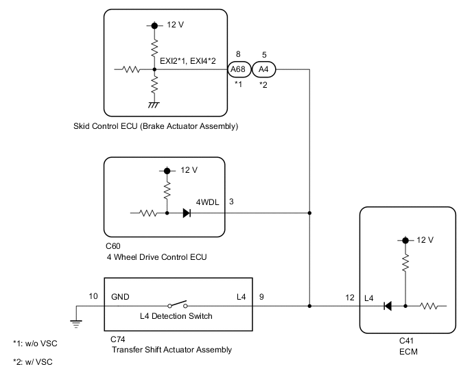
WIRING DIAGRAM
CAUTION / NOTICE / HINT
Tech Tips
After the repair, clear the DTCs and perform the following procedure to check that DTCs are not output.
-
Turn the transfer position switch to H2.
-
Perform the D Position Shift Test in Road Test.
-
Check for DTCs again.
PROCEDURE
-
CHECK SKID CONTROL ECU (BRAKE ACTUATOR ASSEMBLY)
-
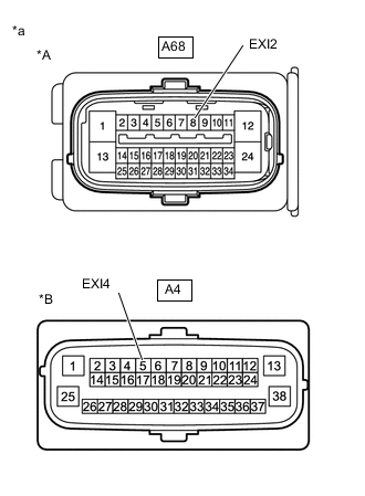
*A w/o VSC *B w/ VSC *a Front view of wire harness connector
(to Skid Control ECU (Brake Actuator Assembly))
Disconnect the A68*1 or A4*2 skid control ECU (brake actuator assembly) connector.
*1: w/o VSC
*2: w/ VSC
-
Measure the resistance according to the value(s) in the table below.
Standard Resistance w/o VSC Tester Connection Switch Condition Specified Condition A68-8 (EXI2) - Body ground Transfer position switch not L4 10 kΩ or higher w/ VSC Tester Connection Switch Condition Specified Condition A4-5 (EXI4) - Body ground Transfer position switch not L4 10 kΩ or higher Result Proceed to OK NG
OK 
GO TO BRAKE CONTROL SYSTEM w/o VSC: GO TO BRAKE CONTROL SYSTEM Click here
GO TO BRAKE CONTROL SYSTEM w/ VSC: GO TO BRAKE CONTROL SYSTEM Click hereNG 
-
-
CHECK TRANSFER SHIFT ACTUATOR ASSEMBLY
-
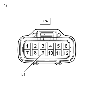
*a Front view of wire harness connector
(to Transfer Shift Actuator Assembly)
Disconnect the C74 transfer shift actuator assembly connector.
-
Disconnect the A68*1 or A4*2 skid control ECU (brake actuator assembly) connector.
*1: w/o VSC
*2: w/ VSC
-
Measure the resistance according to the value(s) in the table below.
Standard Resistance Tester Connection Switch Condition Specified Condition C74-9 (L4) - Body ground Transfer position switch not L4 10 kΩ or higher Result Proceed to OK NG
OK
GO TO TOUCH SELECT 2-4 AND HIGH-LOW SYSTEM Click here
NG
-
-
CHECK 4 WHEEL DRIVE CONTROL ECU
-
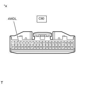
*a Front view of wire harness connector
(to 4 Wheel Drive Control ECU)
Disconnect the C60 4 wheel drive control ECU connector.
-
Disconnect the C74 transfer shift actuator assembly connector.
-
Disconnect the A68*1 or A4*2 skid control ECU (brake actuator assembly) connector.
*1: w/o VSC
*2: w/ VSC
-
Measure the resistance according to the value(s) in the table below.
Standard Resistance Tester Connection Switch Condition Specified Condition C60-3 (4WDL) - Body ground Transfer position switch not L4 10 kΩ or higher Result Proceed to OK NG
OK
GO TO TOUCH SELECT 2-4 AND HIGH-LOW SYSTEM Click here
NG
-
-
CHECK HARNESS AND CONNECTOR (SKID CONTROL ECU (BRAKE ACTUATOR ASSEMBLY), TRANSFER SHIFT ACTUATOR ASSEMBLY, 4 WHEEL DRIVE CONTROL ECU - ECM)
-
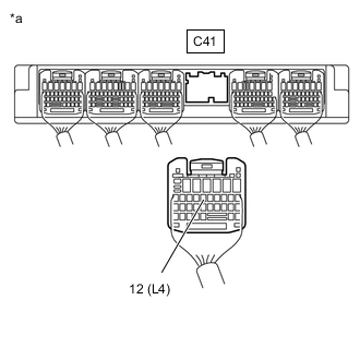
*a Rear view of wire harness connector
(to ECM)
Disconnect the C41 ECM connector.
-
Disconnect the C60 4 wheel drive control ECU connector.
-
Disconnect the C74 transfer shift actuator assembly connector.
-
Disconnect the A68*1 or A4*2 skid control ECU (brake actuator assembly) connector.
*1: w/o VSC
*2: w/ VSC
-
Measure the resistance according to the value(s) in the table below.
Standard Resistance Tester Connection Switch Condition Specified Condition C41-12 (L4) - Body ground Transfer position switch not L4 10 kΩ or higher Result Proceed to OK NG
OK
REPLACE ECM Click here
NG
REPAIR OR REPLACE HARNESS OR CONNECTOR
-