AUTOMATIC TRANSMISSION ASSEMBLY INSTALLATION
PROCEDURE
-
INSTALL TORQUE CONVERTER ASSEMBLY
-
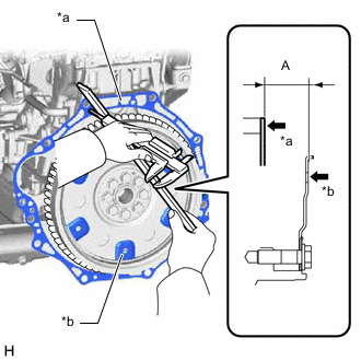
*a Engine Surface *b Drive Plate Surface Using a vernier caliper, measure the dimension (A) between the automatic transmission assembly contact surface of the engine assembly and torque converter assembly contact surface of the drive plate and ring gear sub-assembly.
-
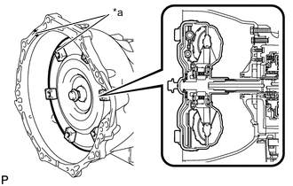
*a Matchmark Align the matchmark on the automatic transmission case sub-assembly with the one on the torque converter assembly and engage the splines of the input shaft with the turbine runner splines.
Note
Install the torque converter assembly to the input shaft while keeping it horizontal.
-
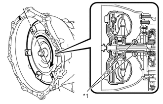
*1 Front Oil Pump Oil Seal Rotate the torque converter assembly approximately 180° and engage the splines of the stator shaft with the stator assembly.
Note
-
Do not damage the front oil pump oil seal.
-
Install the torque converter assembly to the input shaft while keeping it horizontal.
-
-
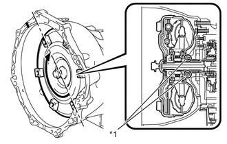
*1 Front Oil Pump Oil Seal Turn the torque converter assembly to engage the key of the oil pump drive gear with the slot on the torque converter assembly.
Note
-
Do not push the torque converter assembly excessively when rotating it.
-
Do not damage the front oil pump oil seal.
-
Install the torque converter assembly to the input shaft while keeping it horizontal.
-
-
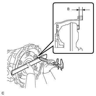
Using a vernier caliper and straightedge, measure the dimension (B) shown in the illustration and check that the dimension (B) is more than the dimension (A), which was measured in the previous step.
Standard B = A + 1.00 mm (0.0394 in.) or more Note
-
Make sure to deduct the thickness of the straightedge.
-
If the automatic transmission assembly is installed to the engine assembly with the torque converter assembly not sufficiently inserted, the torque converter assembly may be damaged.
-
-
-
INSTALL TRANSMISSION BREATHER BRACKET
-
Install the transmission breather bracket with the bolt.
- Torque:
- 6.5 N*m { 66 kgf*cm, 58 in.*lbf }
-
Attach the clamp to connect the automatic transmission breather hose to the transfer breather bracket.
-
-
INSTALL WIRE HARNESS CLAMP BRACKET
-
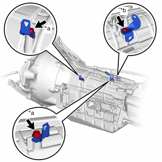
*a Bolt A *b Bolt B Install 3 wire harness clamp brackets with the 3 bolts.
- Torque:
- for bolt A
- 8.0 N*m { 82 kgf*cm, 71 in.*lbf }
- for bolt B
- 12.6 N*m { 128 kgf*cm, 9 ft.*lbf }
-
-
INSTALL TRANSFER ASSEMBLY
-
INSTALL AUTOMATIC TRANSMISSION ASSEMBLY
-
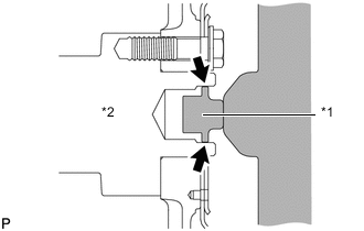
*1 Torque Converter Centerpiece *2 Crankshaft Apply clutch spline grease to the surface of the crankshaft that contacts the torque converter centerpiece.
Clutch spline grease Toyota Genuine Clutch Spline Grease or equivalent Maximum grease amount Approximately 1.0 g (0.0353 oz) -
Confirm that the 2 knock pins are installed on the engine assembly and are not damaged.
-
Install the automatic transmission assembly to the engine with the 5 bolts.
- Torque:
- 71 N*m { 724 kgf*cm, 52 ft.*lbf }
Note
-
Do not use excessive force when installing the automatic transmission assembly.
-
Check that the torque converter assembly rotates.
-
Make sure that the wire harness or other similar items are not pinched between the contact surfaces.
-
Make sure that the cooling fan and fan shroud do not contact the engine assembly when tilting the automatic transmission assembly.
-
-
CONNECT ENGINE WIRE
-
Attach the 7 wire harness clamps and connect the engine wire to the automatic transmission assembly and transfer assembly with the bolt.
- Torque:
- 8.0 N*m { 82 kgf*cm, 71 in.*lbf }
-
Connect the 5 connectors.
Tech Tips
Push up the lever until the claw of the transmission wire connector makes a connection sound.
-
Attach the 5 clamps and connect the transfer breather hose sub-assembly to the automatic transmission assembly.
-
-
INSTALL REAR ENGINE MOUNTING INSULATOR
-
Install the rear engine mounting insulator to the automatic transmission assembly with the 4 bolts.
- Torque:
- 47 N*m { 479 kgf*cm, 35 ft.*lbf }
-
-
INSTALL NO. 3 FRAME CROSSMEMBER SUB-ASSEMBLY
-
Connect the ends of the No. 3 frame crossmember sub-assembly to the body with the 4 bolts and 4 nuts.
- Torque:
- 57 N*m { 581 kgf*cm, 42 ft.*lbf }
Tech Tips
Hold the bolts while tightening the nuts.
-
Connect the No. 3 frame crossmember sub-assembly to the rear engine mounting insulator with the 4 bolts.
- Torque:
- 18.5 N*m { 189 kgf*cm, 14 ft.*lbf }
-
-
INSTALL DRIVE PLATE AND TORQUE CONVERTER ASSEMBLY SETTING BOLT
-
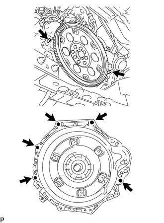
Turn the crankshaft to gain access to the installation locations of the 6 torque converter assembly setting bolts and install each bolt through the hole of the flywheel while holding the crankshaft pulley bolt with a wrench.
- Torque:
- 48 N*m { 489 kgf*cm, 35 ft.*lbf }
Note
Install the black colored bolt first, and then the silver colored 5 bolts.
-
-
INSTALL STIFFENER PLATE
-
Install the No. 2 end plate.
-
Install the No. 4 cylinder block insulator.
-
Install the stiffener plate LH to the engine and automatic transmission assembly with the 4 bolts.
- Torque:
- 71 N*m { 724 kgf*cm, 52 ft.*lbf }
-
Install the stiffener plate RH (with oil cooler tube clamp) to the engine and automatic transmission assembly with the 4 bolts.
- Torque:
- 71 N*m { 724 kgf*cm, 52 ft.*lbf }
-
-
CONNECT GROUND WIRE
-
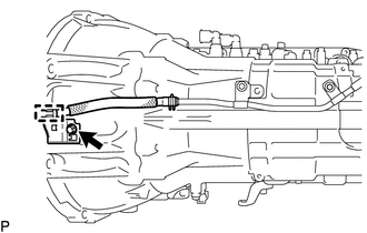
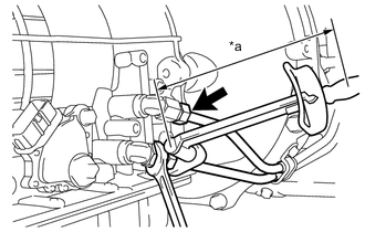
Connect the ground wire to the transfer assembly with the bolt as shown in the illustration.
- Torque:
- 19.5 N*m { 199 kgf*cm, 14 ft.*lbf }
Tech Tips
Make contact with the terminal stopper.
-
-
CONNECT OIL COOLER TUBE
-
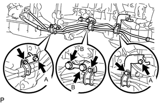
Install the 3 clamps to the automatic transmission assembly and engine assembly with the 4 bolts.
- Torque:
- for bolt A (M8 bolt)
- 13.5 N*m { 138 kgf*cm, 10 ft.*lbf }
- for bolt B (M12 bolt)
- 71 N*m { 724 kgf*cm, 52 ft.*lbf }
Tech Tips
It is not necessary to remove the clamp unless they are being replaced.
-
Connect the end of the inlet oil cooler tube to the automatic transmission assembly by hand.
-
Connect the end of the outlet oil cooler tube to the automatic transmission assembly by hand.
-
Install the 3 oil cooler tube clamps with the 3 bolts.
- Torque:
- 5.5 N*m { 56 kgf*cm, 49 in.*lbf }
-
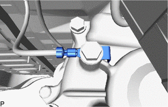
*a Torque Wrench Fulcrum Length Using a 17 mm union nut wrench, tighten the oil cooler tube inlet and oil cooler tube outlet.
Specified tightening torque 34.3 N*m (350 kgf*cm, 25 ft.*lbf) Tech Tips
-
Calculate the torque wrench reading when changing the fulcrum length of the torque wrench.
-
When using a union nut wrench (fulcrum length of 30 mm (1.18 in.)) + torque wrench (fulcrum length of 300 mm (11.8 in.)): 31.2 N*m (318 kgf*cm, 23 ft.*lbf)
-
-
-
INSTALL TRANSMISSION CONTROL CABLE BRACKET
-
Install the transmission control cable bracket with the 2 bolts.
- Torque:
- 14 N*m { 143 kgf*cm, 10 ft.*lbf }
-
-
CONNECT TRANSMISSION CONTROL CABLE ASSEMBLY
-
Move the shift lever to N.
-
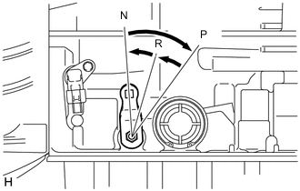
Turn the transmission control shaft lever clockwise until it stops, and then turn it counterclockwise 2 notches to set it to the N position.
-
Connect the transmission control cable assembly to the transmission control cable bracket with a new clip, and then connect the cable end to the transmission control shaft lever LH with the nut.
- Torque:
- 14 N*m { 143 kgf*cm, 10 ft.*lbf }
-
-
INSTALL FRONT EXHAUST PIPE ASSEMBLY
-
INSTALL STARTER ASSEMBLY
-
for 2.0 kW Type:
-
for BOSCH Made:
-
-
INSTALL PROPELLER SHAFT WITH CENTER BEARING ASSEMBLY
-
for TSAM Made:
-
for TMMIN Made:
-
-
INSTALL FRONT DIFFERENTIAL CARRIER ASSEMBLY
-
ADD TRANSFER OIL
-
ADD AUTOMATIC TRANSMISSION FLUID
-
CONNECT CABLE TO NEGATIVE BATTERY TERMINAL
Note
When disconnecting the cable, some systems need to be initialized after the cable is reconnected.
-
INSPECT SHIFT LEVER POSITION
-
ADJUST AUTOMATIC TRANSMISSION FLUID
-
INSPECT FOR EXHAUST GAS LEAK
-
INSPECT FOR OIL LEAK
-
Start the engine. Make sure that there are no oil leaks from the areas that were worked on.
-
-
RESET MEMORY
Note
If automatic transmission parts have been replaced, refer to the Parts Replacement Compensation Table to determine if any additional operations are necessary.