AUTOMATIC TRANSMISSION SYSTEM DIAGNOSIS SYSTEM

-
M-OBD (EXCEPT EUROPEAN SPECIFICATION)
-
When troubleshooting Multiplex On-Board Diagnostic (M-OBD) vehicles, the vehicle must be connected to the GTS. Various data output from the TCM can then be read.
-
OBD regulations require that the vehicle's on-board computer illuminate the MIL on the instrument panel when the computer detects a malfunction in:
-
The emission control system/components.
-
The powertrain control components which affect vehicle emissions.
-
The computer itself.
In addition, the applicable DTCs are stored in the TCM memory.
If the malfunction does not reoccur in 3 consecutive trips, the MIL turns off automatically but the DTCs remain stored in the TCM memory.
-
-
-
NORMAL MODE AND CHECK MODE
The diagnosis system operates in normal mode during normal vehicle use. In normal mode, 2-trip detection logic is used to ensure accurate detection of malfunctions. Check mode is also available to technicians as an option. In check mode, 1-trip detection logic is used to increase the ability of the system to detect malfunctions, including intermittent malfunctions, when reproducing malfunction symptoms (GTS only).
-
2-TRIP DETECTION LOGIC
-
When a malfunction is first detected, the malfunction is temporarily stored in the TCM memory (1st trip). If the ignition switch is turned off and then turned ON again, and the same malfunction is detected again, the MIL illuminates.
-
-
FREEZE FRAME DATA
-
The TCM records vehicle and driving condition information as freeze frame data the moment a DTC is stored. When troubleshooting, freeze frame data can be helpful in determining whether the vehicle was moving or stationary, whether the engine was warmed up or not, whether the air-fuel ratio was lean or rich, as well as other data recorded at the time of a malfunction.
-
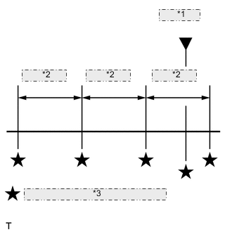
*1 DTC stored *2 0.5 seconds *3 Freeze frame data which can be read The GTS displays freeze frame data recorded at five different points: 1) 3 times before the DTC is stored, 2) once when the DTC is stored, and 3) once after the DTC is stored. The data can be used to reproduce the vehicle condition from around the time of the malfunction. The data may be helpful in determining the cause of a malfunction. It may also be helpful in determining whether a DTC is being caused by a temporary malfunction.
-
-
CHECK DATA LINK CONNECTOR 3 (DLC3)
-
Check the DLC3.
-
-
CHECK BATTERY VOLTAGE
If the voltage is below 11 V, replace the battery before proceeding.
-
CHECK MIL
-
Check that the MIL illuminates when the ignition switch is turned to ON.
If the MIL does not illuminate, there is a problem in the MIL circuit.
-
Check that when the engine is started, the MIL goes off.
-