AUTOMATIC TRANSMISSION SYSTEM, Diagnostic DTC:P0500

| DTC Code | DTC Name |
|---|---|
| P0500 | Vehicle Speed Sensor Malfunction |
DESCRIPTION
The speed sensor detects the wheel speed and sends the appropriate signals to the skid control ECU. The skid control ECU converts these wheel speed signals into a pulse signal and outputs it to the TCM via the combination meter. The TCM determines the vehicle speed based on the frequency of this pulse signal.
| DTC No. | Detection Item | DTC Detection Condition | Trouble Area | MIL | Memory |
|---|---|---|---|---|---|
| P0500 | Vehicle Speed Sensor Malfunction | While the vehicle is being driven at 9 km/h (5.59 mph) or more, no vehicle speed sensor signal is transmitted to the TCM for 5 seconds or more (2-trip detection logic). |
|
Comes on | DTC stored |
MONITOR DESCRIPTION
The TCM assumes that the vehicle is being driven when the indicated vehicle speed is more than 9 km/h (5.59 mph). If there is no speed signal from the combination meter despite this condition being met, the TCM interprets this as a malfunction in the speed signal circuit. The TCM then illuminates the MIL and stores the DTC.
WIRING DIAGRAM
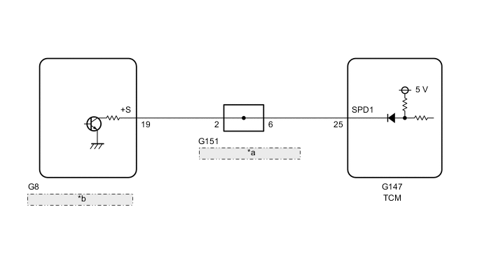
| *a | No. 32 Junction Connector |
| *b | Combination Meter Assembly |
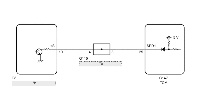
| *a | No. 14 Junction Connector |
| *b | Combination Meter Assembly |
CAUTION / NOTICE / HINT
Tech Tips
After the repair, clear the DTCs and perform the following procedure to check that DTCs are not output.
-
Turn the ignition switch to ON and wait for 3 seconds or more.*1
-
Drive the vehicle at 9 km/h (5.59 mph) or more for 5 seconds or more.*2
-
Turn the ignition switch off.
-
Perform steps (*1) through (*2) again.
-
Check for DTCs again.
PROCEDURE
-
READ VALUE USING GTS (VEHICLE SPEED)
-
Drive the vehicle and check whether the operation of the speedometer in the combination meter assembly is normal.
Tech Tips
-
The vehicle speed sensor is operating normally if the speedometer reading is normal.
-
If the speedometer does not operate, check it by following the procedure described for a speedometer malfunction.
-
-
Connect the GTS to the DLC3.
-
Turn the ignition switch to ON.
-
Turn the GTS on.
-
Enter the following menus: Powertrain / ECT / Data List.
-
Drive the vehicle.
-
Read the value displayed on the GTS.
Powertrain > ECT > Data ListTester Display Measurement Item Range Normal Condition Diagnostic Note Vehicle Speed Vehicle speed Min.: 0 km/h (0 mph)
Max.: 255 km/h (158 mph)
Actual vehicle speed -
Powertrain > ECT > Data ListTester Display Vehicle Speed OK Vehicle speed displayed on the GTS and speedometer display are equal. Result Proceed to OK NG
OK 
CHECK FOR INTERMITTENT PROBLEMS Click here
NG 
-
-
CHECK COMBINATION METER SYSTEM
-
Inspect the circuits that send vehicle speed signals to this system in the meter system.
-
During inspection for the meter section, if there is an instruction that indicates to go back to inspections for each system, proceed to the next step.
Result Proceed to NEXT
NEXT
-
-
CHECK HARNESS AND CONNECTOR (COMBINATION METER ASSEMBLY - TCM)
-
Disconnect the G8 combination meter assembly connector.
-
Disconnect the G147 TCM connector.
-
Measure the resistance according to the value(s) in the table below.
Standard Resistance Tester Connection Condition Specified Condition G8-19 (+S) - G147-25 (SPD1) Always Below 1 Ω Result Proceed to OK NG
OK
REPLACE TCM Click here
NG
-
-
CHECK HARNESS AND CONNECTOR (JUNCTION CONNECTOR - TCM)
-
for LHD:
Disconnect the G151 NO. 32 junction connector.
-
for RHD:
Disconnect the G115 NO. 14 junction connector.
-
Disconnect the G147 TCM connector.
-
Measure the resistance according to the value(s) in the table below.
Standard Resistance for LHD: Tester Connection Condition Specified Condition G151-6 - G147-25 (SPD1) Always Below 1 Ω for RHD: Tester Connection Condition Specified Condition G115-8 - G147-25 (SPD1) Always Below 1 Ω Result Proceed to OK NG
OK
REPAIR OR REPLACE JUNCTION CONNECTOR
NG
REPAIR OR REPLACE HARNESS OR CONNECTOR
-