CRUISE CONTROL SYSTEM, Diagnostic DTC:P0571
| DTC Code | DTC Name |
|---|---|
| P0571 | Brake Switch "A" Circuit |
DESCRIPTION
When the brake pedal is depressed, the stop light switch assembly sends a signal to the ECM. Upon receiving the signal, the ECM cancels the cruise control system.
| DTC No. | Detection Item | DTC Detection Condition | Trouble Area |
|---|---|---|---|
| P0571 | Brake Switch "A" Circuit | When voltage of STP terminal and that of ST1- terminal of ECM are less than 1 V for 0.5 seconds or more |
|
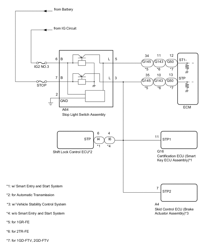
WIRING DIAGRAM
CAUTION / NOTICE / HINT
Note
Inspect the fuses for circuits related to this system before performing the following procedure.
PROCEDURE
-
CHECK HARNESS AND CONNECTOR (STOP LIGHT SWITCH ASSEMBLY - BATTERY AND BODY GROUND)
-
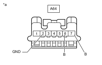
*a Front view of wire harness connector
(to Stop Light Switch Assembly)
Disconnect the stop light switch assembly connector.
-
Measure the resistance according to the value(s) in the table below.
Standard Resistance Tester Connection Condition Specified Condition A64-2 (GND) -Body ground Always Below 1 Ω -
Measure the voltage according to the value(s) in the table below.
Standard Voltage Tester Connection Condition Specified Condition A64-6 (B) - Body ground Ignition switch off Below 1 V Ignition switch ON 11 to 14 V A64-7 (B) - Body ground Always 11 to 14 V Result Proceed to OK NG
NG 
REPAIR OR REPLACE HARNESS OR CONNECTOR (STOP LIGHT SWITCH ASSEMBLY - BATTERY AND BODY GROUND)
OK 
-
-
CHECK HARNESS AND CONNECTOR (ECM - STOP LIGHT SWITCH ASSEMBLY)
-
Disconnect the A64 stop light switch assembly connector.
-
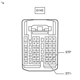
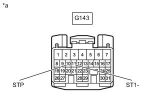
Disconnect the G145*1, G143*2 or G50*3 ECM connector.
-
*1: for 1GR-FE
-
*2: for 2TR-FE
-
*3: for 1GD-FTV, 2GD-FTV
-
-
for Automatic Transmission:
-
w/ Smart Entry and Start System:
Disconnect the I4 shift lock control ECU connector.
-
w/o Smart Entry and Start System:
Disconnect the I6 shift lock control ECU connector.
-
-
w/ Vehicle Stability Control System:
Disconnect the A4 skid control ECU (brake actuator assembly) connector.
-
w/ Smart Entry and Start System:
Disconnect the G16 certification ECU (smart key ECU assembly) connector.
-
Measure the resistance according to the value(s) in the table below.
-
for 1GR-FE:
Standard Resistance Tester Connection Condition Specified Condition G145-34 (ST1-) - A64-5 (L) Always Below 1 Ω G145-35 (STP) - A64-3 (L) Always Below 1 Ω G145-34 (ST1-) or A64-5 (L) - Body ground Always 10 kΩ or higher G145-35 (STP) or A64-3 (L) - Body ground Always 10 kΩ or higher -
for 2TR-FE:
Standard Resistance Tester Connection Condition Specified Condition G143-11 (ST1-) - A64-5 (L) Always Below 1 Ω G143-10 (STP) - A64-3 (L) Always Below 1 Ω G143-11 (ST1-) or A64-5 (L) - Body ground Always 10 kΩ or higher G143-10 (STP) or A64-3 (L) - Body ground Always 10 kΩ or higher -
for 1GD-FTV, 2GD-FTV:
Standard Resistance Tester Connection Condition Specified Condition G50-12 (ST1-) - A64-5 (L) Always Below 1 Ω G50-13 (STP) - A64-3 (L) Always Below 1 Ω G50-12 (ST1-) or A64-5 (L) - Body ground Always 10 kΩ or higher G50-13 (STP) or A64-3 (L) - Body ground Always 10 kΩ or higher
Result Proceed to OK NG -
NG
REPAIR OR REPLACE HARNESS OR CONNECTOR (ECM - STOP LIGHT SWITCH ASSEMBLY)
OK
-
-
CHECK STOP LIGHT SWITCH OUTPUT VOLTAGE
-
for 1GR-FE
-
*a Front view of wire harness connector
(to ECM)
Disconnect the ECM connector.
-
Measure the voltage according to the value(s) in the table below.
Standard Voltage Tester Connection Condition Specified Condition G145-34 (ST1-) - Body ground Ignition switch ON, brake pedal depressed Below 1.5 V Ignition switch ON, brake pedal released 7.5 to 14 V G145-35 (STP) - Body ground Brake pedal depressed 7.5 to 14 V Brake pedal released Below 1.5 V
-
-
for 2TR-FE
-
*a Front view of wire harness connector
(to ECM)
Disconnect the ECM connector.
-
Measure the voltage according to the value(s) in the table below.
Standard Voltage Tester Connection Condition Specified Condition G143-11 (ST1-) - Body ground Ignition switch ON, brake pedal depressed Below 1.5 V Ignition switch ON, brake pedal released 7.5 to 14 V G143-10 (STP) - Body ground Brake pedal depressed 7.5 to 14 V Brake pedal released Below 1.5 V
-
-
for 1GD-FTV, 2GD-FTV
-
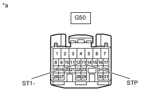
*a Front view of wire harness connector
(to ECM)
Disconnect the ECM connector.
-
Measure the voltage according to the value(s) in the table below.
Standard Voltage Tester Connection Condition Specified Condition G50-12 (ST1-) - Body ground Ignition switch ON, brake pedal depressed 0 to 1.5 V Ignition switch ON, brake pedal released 7.5 to 14 V G50-13 (STP) - Body ground Brake pedal depressed 7.5 to 14 V Brake pedal released 0 to 1.5 V
Result Proceed to OK NG -
OK
REPLACE ECM for 1GR-FE: Click here
REPLACE ECM for 2TR-FE: Click here
REPLACE ECM for 1GD-FTV: Click here
REPLACE ECM for 2GD-FTV: Click hereNG
REPLACE STOP LIGHT SWITCH ASSEMBLY Click here
-