CRUISE CONTROL SYSTEM TERMINALS OF ECM
-
CHECK ECM
-
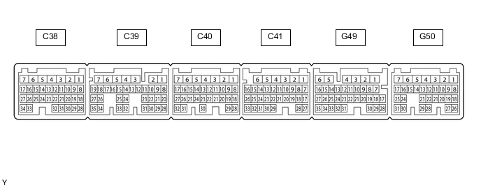
Disconnect the C38, C41, G49 and G50 ECM connectors.
-
Measure the resistance and voltage according to the value(s) in the table below.
Terminal No. (Symbol) Wiring Color Terminal Description Condition Specified Condition C38-14 (D) - C41-1 (E1)*1 GR - W-B Clutch switch signal Ignition switch ON, clutch pedal depressed Below 1 V Ignition switch ON, clutch pedal released 11 to 14 V C38-14 (D) - C41-1 (E1)*2 GR - W-B D shift position signal Ignition switch ON, shift lever in D 11 to 14 V Ignition switch ON, shift lever is not in D Below 1 V C41-1 (E1) - Body ground W-B - Body ground Ground Always Below 1 Ω G49-13 (S) - C41-1 (E1) L - W-B S shift position switch signal Ignition switch ON and shift lever in S 11 to 14 V Ignition switch ON, shift lever is not in S Below 1 V G49-20 (SFTD) - C41-1 (E1) G - W-B Down-shift switch signal Ignition switch ON and shift lever in S 11 to 14 V Ignition switch ON and shift lever in "-" position (down-shift) Below 1 V G49-21 (SFTU) - C41-1 (E1) W - W-B Up-shift switch signal Ignition switch ON and shift lever in S 11 to 14 V Ignition switch ON and shift lever in "+" position (up-shift) Below 1 V G49-20 (SFTD) - C41-1 (E1)*3 G - W-B Down-shift switch signal Ignition switch ON and shift lever in D or S 11 to 14 V Ignition switch ON and "-" shift paddle operated and held (down-shift) Below 1 V G49-21 (SFTU) - C41-1 (E1)*3 W - W-B Up-shift switch signal Ignition switch ON and shift lever in D or S 11 to 14 V Ignition switch ON and "+" shift paddle operated and held (up-shift) Below 1 V G50-1 (BATT) - Body ground Y - Body ground Constant power source Always 11 to 14 V G50-12 (ST1-) - C41-1 (E1) GR - W-B Stop light signal Ignition switch ON, brake pedal depressed 0 to 1.5 V Ignition switch ON, brake pedal released 7.5 to 14 V G50-13 (STP) - C41-1 (E1) L - W-B Stop light signal Brake pedal depressed 7.5 to 14 V Brake pedal released 0 to 1.5 V G50-26 (CCS) - C41-1 (E1) G - W-B Cruise control switch circuit Cruise control switch off 1 MΩ or higher Cruise control switch on Below 2.5 Ω +RES switch on 235 to 245 Ω -SET switch on 617 to 643 Ω CANCEL switch on 1509 to 1571 Ω
-
*1: for Manual Transmission
-
*2: for Automatic Transmission
-
*3: w/ Transmission Shift Switch
-
-