OIL PUMP INSPECTION

PROCEDURE
-
INSPECT OIL PUMP RELIEF VALVE
-
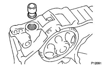
Coat the oil pump relief valve with engine oil and drop it into the oil pump relief valve hole.
-
Check that the oil pump relief valve falls in smoothly by its own weight.
If it does not, replace the oil pump relief valve. If necessary, replace the timing gear case assembly.
-
-
INSPECT OIL PUMP
-
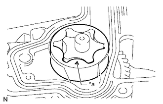
*a Alignment Mark Install the driven rotor to the timing gear case assembly with the mark facing the cylinder block side.
-
Check the tip clearance.
-
Using a feeler gauge, measure the clearance between the drive rotor and driven rotor tips.
Standard tip clearance 0.06 to 0.16 mm (0.00236 to 0.00630 in.) Maximum tip clearance 0.21 mm (0.00827 in.) If the tip clearance is more than the maximum, replace the timing gear case assembly.
-
-

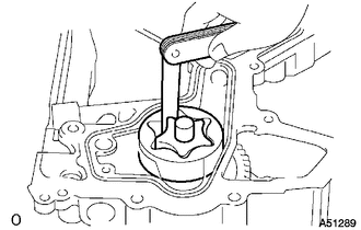
Check the body clearance.
-
Using a feeler gauge, measure the clearance between the oil pump body and driven rotor.
Standard body clearance 0.10 to 0.17 mm (0.00394 to 0.00669 in.) Maximum body clearance 0.2 mm (0.00787 in.) If the body clearance is more than the maximum, replace the timing gear case assembly.
-
-
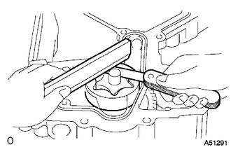
Check the side clearance.
-
Using a feeler gauge and precision straightedge, measure the clearance between the rotor and precision straightedge.
Standard side clearance 0.03 to 0.09 mm (0.00118 to 0.00354 in.) Maximum side clearance 0.15 mm (0.00591 in.) If the side clearance is more than the maximum, replace the timing gear case assembly.
-
-