OIL PUMP INSTALLATION

CAUTION / NOTICE / HINT
Note
-
When replacing the parts in the following chart (A), replace the No. 1 injection pipe sub-assembly, No. 2 injection pipe sub-assembly, No. 3 injection pipe sub-assembly, No. 4 injection pipe sub-assembly and/or fuel inlet pipe sub-assembly with new ones.
Replaced Parts (A) Pipes Requiring New Replacement
-
Injector assembly (including shuffling the injector assemblies between the cylinders)
-
Common rail assembly
-
Cylinder head sub-assembly
-
No. 1 injection pipe sub-assembly
-
No. 2 injection pipe sub-assembly
-
No. 3 injection pipe sub-assembly
-
No. 4 injection pipe sub-assembly
-
Supply pump assembly
-
Common rail assembly
-
Cylinder block sub-assembly
-
Cylinder head sub-assembly
-
Cylinder head gasket
-
Timing Gear Case Assembly
Fuel inlet pipe sub-assembly -
-
After removing the No. 1 injection pipe sub-assembly, No. 2 injection pipe sub-assembly, No. 3 injection pipe sub-assembly, No. 4 injection pipe sub-assembly and fuel inlet pipe sub-assembly, clean them with a brush and compressed air.
PROCEDURE
-
INSTALL TIMING GEAR CASE ASSEMBLY
-
INSTALL OIL STRAINER SUB-ASSEMBLY
-
INSTALL OIL PAN SUB-ASSEMBLY
-
INSTALL FUEL SUPPLY PUMP ASSEMBLY
-
INSTALL INJECTION GEAR
-
INSTALL CRANKSHAFT TIMING GEAR
-
INSTALL NO. 1 IDLE GEAR SHAFT
-
INSTALL NO. 1 IDLE GEAR
-
INSTALL NO. 1 CRANKSHAFT POSITION SENSOR PLATE
-
INSTALL TIMING GEAR COVER
-
INSTALL CRANKSHAFT PULLEY SUB-ASSEMBLY
-
INSTALL PUMP DRIVE SHAFT PULLEY
-
Install a new O-ring to the fuel supply pump assembly.
-
Temporarily install the fuel supply pump assembly with the nut.
-
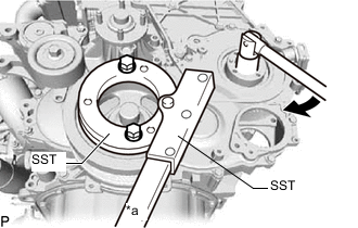
*a Hold 
Turn Using SST, hold the crankshaft pulley and tighten the nut.
- SST
- 09213-58014 ( 91551-80840 )
- 09330-00021
- Torque:
- 63.7 N*m { 650 kgf*cm, 47 ft.*lbf }
-
Install the No. 2 camshaft timing pulley flange and pump drive shaft pulley to the timing gear cover with the 4 bolts.
- Torque:
- 31 N*m { 316 kgf*cm, 23 ft.*lbf }
-
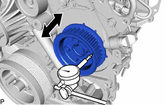
Using a dial indicator, check the thrust clearance of the pump drive shaft while moving the pump drive shaft pulley back and forth.
Standard thrust clearance (reference) 0.15 to 0.55 mm (0.00591 to 0.0217 in.) Tech Tips
If there is no clearance, remove and reinstall the fuel supply pump assembly and pump drive shaft pulley. Then repeat the step above.
-
-
INSTALL CRANKSHAFT POSITION SENSOR
-
INSTALL CAMSHAFT POSITION SENSOR
-
INSTALL VANE PUMP ASSEMBLY
-
INSTALL VACUUM PUMP ASSEMBLY
-
INSTALL ENGINE WATER PUMP ASSEMBLY
-
INSTALL NO. 2 TIMING BELT COVER
-
INSTALL CAMSHAFT TIMING PULLEY
-
INSTALL CYLINDER HEAD COVER SUB-ASSEMBLY
-
INSTALL NO. 2 NOZZLE LEAKAGE PIPE ASSEMBLY
-
INSTALL FUEL INLET PIPE SUB-ASSEMBLY
-
INSTALL NO. 4 INJECTION PIPE SUB-ASSEMBLY
-
INSTALL NO. 1, NO. 2 AND NO. 3 INJECTION PIPE SUB-ASSEMBLY
-
INSTALL ENGINE OIL LEVEL DIPSTICK GUIDE
-
INSTALL MANIFOLD STAY
-
INSTALL NO. 1 COMPRESSOR MOUNTING BRACKET
-
INSTALL V-RIBBED BELT TENSIONER ASSEMBLY
-
INSTALL GENERATOR BRACKET
-
INSTALL GENERATOR ASSEMBLY
-
INSTALL NO. 2 IDLE PULLEY ASSEMBLY
-
INSTALL NO. 1 TIMING BELT IDLER SUB-ASSEMBLY
-
INSTALL TIMING BELT
-
INSTALL NO. 1 TIMING BELT COVER
-
INSTALL ENGINE ASSEMBLY
-
ADD ENGINE OIL
-
CONNECT CABLE TO NEGATIVE BATTERY TERMINAL
Note
When disconnecting the cable, some systems need to be initialized after the cable is reconnected.
-
BLEED AIR FROM FUEL SYSTEM
-
ADD ENGINE COOLANT
-
BLEED AIR FROM POWER STEERING SYSTEM
-
INSPECT FOR POWER STEERING FLUID LEVEL
-
PERFORM REGISTRATION
-
Perform registration of the injector compensation codes.
-
Perform pilot quantity learning.
-
-
INSPECT FOR OIL LEAK
-
INSPECT FOR COOLANT LEAK
-
INSPECT FOR EXHAUST GAS LEAK
-
INSPECT FOR FUEL LEAK
-
INSPECT ENGINE OIL LEVEL