OIL PUMP INSTALLATION

PROCEDURE
-
INSTALL TIMING CHAIN COVER SUB-ASSEMBLY
-
Clean and degrease the contact surfaces of the timing chain cover sub-assembly, cylinder head LH, cylinder head sub-assembly and cylinder block sub-assembly.
-
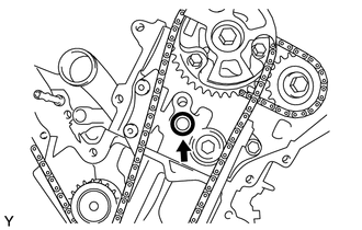
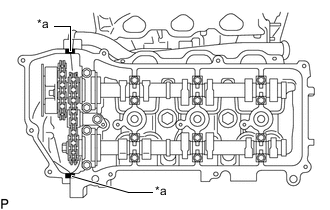
Install a new O-ring to the cylinder head LH as shown in the illustration.
-
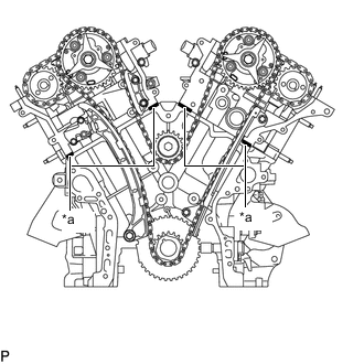
*a Seal Packing Application Area Apply seal packing as shown in the illustration.
Seal packing Toyota Genuine Seal Packing Black, Three Bond 1207B or equivalent Standard seal diameter 3.5 to 4.5 mm (0.138 to 0.177 in.) -
Apply seal packing as shown in the illustration.
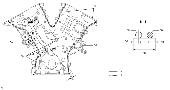
*a Seal Packing *b Continuous line area *c Dashed line area *d 3.0 to 4.0 mm (0.118 to 0.157 in.) *e 16.7 mm (0.657 in.) - - Seal packing Continuous line area Toyota Genuine Seal Packing Black, Three Bond 1207B or equivalent Dashed line area Toyota Genuine Seal Packing 1282B, Three Bond 1282B or equivalent Standard seal diameter 3.5 to 4.5 mm (0.138 to 0.177 in.) Note
-
Install the timing chain cover sub-assembly within 3 minutes after applying seal packing. After installing it, the bolts and nuts must be tightened within 15 minutes. Otherwise the seal packing must be removed and reapplied.
-
Do not apply seal packing to "A" shown in the illustration.
-
-
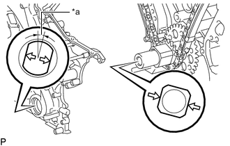
*a 15° Align the width of the joint portion of the oil pump drive rotor and the crankshaft timing gear, and then install the timing chain cover sub-assembly.
-
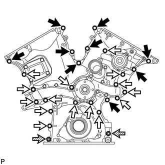

Bolt A 
Bolt B 
Nut Install the timing chain cover sub-assembly with the 24 bolts and 2 nuts. Tighten the bolts and nuts uniformly in several steps.
- Torque:
- for bolt
- 21 N*m { 214 kgf*cm, 15 ft.*lbf }
- for nut
- 23 N*m { 235 kgf*cm, 17 ft.*lbf }
Standard Bolt Item Length Bolt A 25 mm (0.984 in.) Bolt B 55 mm (2.17 in.) Note
-
Make sure not to wrap the chain and slipper over the timing chain cover seal line.
-
Make sure that there is no oil on the bolt threads.
-
-
INSTALL FRONT CRANKSHAFT OIL SEAL
-
INSTALL OIL FILTER BRACKET SUB-ASSEMBLY
-
Install a new gasket and the oil filter bracket sub-assembly with the 3 bolts and 2 nuts.
- Torque:
- 19 N*m { 194 kgf*cm, 14 ft.*lbf }
-
-
INSTALL OIL FILTER SUB-ASSEMBLY
-
INSTALL CYLINDER HEAD COVER SUB-ASSEMBLY LH
-
Clean and degrease the contact surfaces of the timing chain cover sub-assembly and cylinder head LH.
-
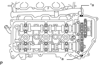
*a Seal Packing Application Area Apply seal packing as shown in the illustration.
Seal packing Toyota Genuine Seal Packing Black, Three Bond 1207B or equivalent Standard seal diameter 2.0 to 3.0 mm (0.0787 to 0.118 in.) Note
Install the cylinder head cover sub-assembly LH within 3 minutes after applying seal packing. After installing it, the bolts and nuts must be tightened within 15 minutes. Otherwise the seal packing must be removed and reapplied.
-
Install a new cylinder head cover gasket to the cylinder head cover sub-assembly LH.
-
Install new seal washers to the bolts.
-
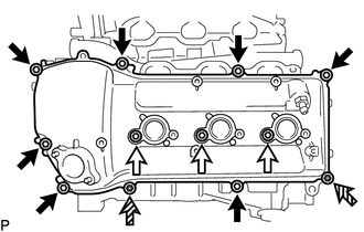
Bolt A Bolt B Nut Temporarily install the cylinder head cover sub-assembly LH with the 10 bolts and 2 nuts. Tighten the bolts and nuts uniformly in several steps.
- Torque:
- for bolt A
- 10 N*m { 102 kgf*cm, 7 ft.*lbf }
- for bolt B and nut
- 9.0 N*m { 92 kgf*cm, 80 in.*lbf }
Standard Bolt Item Length Bolt A 25 mm (0.984 in.) Bolt B 60 mm (2.36 in.)
-
-
INSTALL CYLINDER HEAD COVER SUB-ASSEMBLY
-
Clean and degrease the contact surfaces of the timing chain cover sub-assembly and cylinder head sub-assembly.
-
*a Seal Packing Application Area Apply seal packing as shown in the illustration.
Seal packing Toyota Genuine Seal Packing Black, Three Bond 1207B or equivalent Standard seal diameter 2.0 to 3.0 mm (0.0787 to 0.118 in.) Note
Install the cylinder head cover sub-assembly within 3 minutes after applying seal packing. After installing it, bolts and nuts must be tightened within 15 minutes. Otherwise the seal packing must be removed and reapplied.
-
Install a new cylinder head cover gasket to the cylinder head cover sub-assembly.
-
Install new seal washers to the bolts.
-
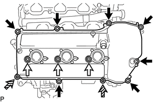
Bolt A Bolt B Nut Temporarily install the cylinder head cover sub-assembly with the 10 bolts and 2 nuts. Tighten the bolts and nuts uniformly in several steps.
- Torque:
- for bolt A
- 10 N*m { 102 kgf*cm, 7 ft.*lbf }
- for bolt B and nut
- 9.0 N*m { 92 kgf*cm, 80 in.*lbf }
Standard Bolt Length Item Specified Condition Bolt A 25 mm (0.984 in.) Bolt B 60 mm (2.36 in.)
-
-
INSTALL NO. 1 FUEL PIPE SUB-ASSEMBLY AND NO. 2 FUEL PIPE SUB-ASSEMBLY
-
INSTALL OIL PAN SUB-ASSEMBLY
-
Clean and degrease the contact surfaces of the cylinder block, rear oil seal retainer and oil pan sub-assembly.
-
Install a new O-ring to the timing chain cover sub-assembly.
-
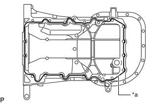
*a Seal Packing Application Area Apply seal packing as shown in the illustration.
Seal packing Toyota Genuine Seal Packing Black, Three Bond 1207B or equivalent Standard seal diameter 3.0 to 4.0 mm (0.118 to 0.157 in.) Note
-
Remove any oil from the contact surface.
-
Install the oil pan sub-assembly within 3 minutes after applying seal packing. After installing the oil pan sub-assembly, the bolts and nuts must be tightened within 15 minutes. Otherwise the seal packing must be removed and reapplied.
-
Do not start the engine for at least 2 hours after installing.
-
-
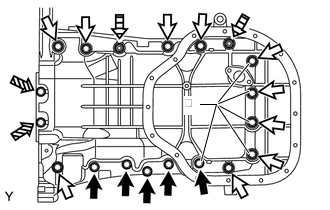
Bolt A Bolt B Bolt C 
Nut Install the oil pan sub-assembly with the 17 bolts and 2 nuts. Tighten the bolts and nuts uniformly in several steps.
- Torque:
- except bolt C
- 21 N*m { 214 kgf*cm, 15 ft.*lbf }
- for bolt C
- 10 N*m { 102 kgf*cm, 7 ft.*lbf }
Adhesive Toyota Genuine Adhesive 1324, Three Bond 1324 or equivalent Standard Bolt Item Length Bolt A 25 mm (0.984 in.) Bolt B 45 mm (1.77 in.) Bolt C 16 mm (0.630 in.) Note
The bolts indicated by stars in the illustration are precoated parts. When reusing these bolts, apply adhesive to 2 or 3 threads before installation.
-
-
INSTALL OIL STRAINER SUB-ASSEMBLY
-
Install a new gasket and the oil strainer sub-assembly with the bolt and 2 nuts.
- Torque:
- 9.0 N*m { 92 kgf*cm, 80 in.*lbf }
-
-
INSTALL NO. 2 OIL PAN SUB-ASSEMBLY
-
Clean and degrease the contact surfaces of the oil pan sub-assembly and No. 2 oil pan sub-assembly.
-
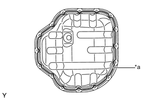
*a Seal Packing Application Area Apply seal packing as shown in the illustration.
Seal packing Toyota Genuine Seal Packing Black, Three Bond 1207B or equivalent Standard seal diameter 3.0 to 4.0 mm (0.118 to 0.157 in.) Note
-
Remove any oil from the contact surface.
-
Install the No. 2 oil pan sub-assembly within 3 minutes after applying seal packing. After installing the No. 2 oil pan, the bolts and nuts must be tightened within 15 minutes. Otherwise the seal packing must be removed and reapplied.
-
Do not start the engine for at least 4 hours after the installation.
-
-
Install the No. 2 oil pan sub-assembly with the 14 bolts and 2 nuts. Tighten the bolts and nuts uniformly in several steps.
- Torque:
- for bolt
- 9.0 N*m { 92 kgf*cm, 80 in.*lbf }
- for nut
- 10 N*m { 102 kgf*cm, 7 ft.*lbf }
-
-
INSTALL CRANKSHAFT PULLEY
-
Align the key groove of the crankshaft pulley with the pulley set key and slide on the crankshaft pulley.
-
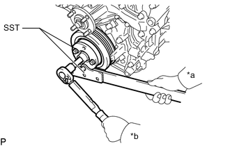
*a Hold *b Turn Using SST, install the crankshaft pulley with the crankshaft pulley set bolt.
- SST
- 09213-54015 ( 91651-60855 )
- 09330-00021
- Torque:
- 250 N*m { 2549 kgf*cm, 184 ft.*lbf }
-
-
INSTALL NO. 1 IDLER PULLEY SUB-ASSEMBLY
-
INSTALL NO. 2 IDLER PULLEY SUB-ASSEMBLY
-
INSTALL V-RIBBED BELT TENSIONER ASSEMBLY
-
INSTALL WATER INLET ASSEMBLY
-
INSTALL ENGINE OIL LEVEL DIPSTICK GUIDE
-
INSTALL IGNITION COIL ASSEMBLY
-
INSTALL CAMSHAFT TIMING OIL CONTROL VALVE ASSEMBLY (for Bank 2)
-
INSTALL CAMSHAFT TIMING OIL CONTROL VALVE ASSEMBLY (for Bank 1)
-
INSTALL VVT SENSOR (for Bank 2)
-
INSTALL VVT SENSOR (for Bank 1)
-
REMOVE ENGINE FROM ENGINE STAND
-
INSTALL ENGINE ASSEMBLY