WATER PUMP(When Not Using the Variable Pin Wrench) REMOVAL
CAUTION / NOTICE / HINT
Note
-
When replacing the parts in the following chart (A), replace the No. 1 injection pipe sub-assembly, No. 2 injection pipe sub-assembly, No. 3 injection pipe sub-assembly, No. 4 injection pipe sub-assembly and/or fuel inlet pipe sub-assembly with new ones.
Replaced Parts (A) Pipes Requiring New Replacement
-
Injector assembly (including shuffling the injector assemblies between the cylinders)
-
Common rail assembly
-
Cylinder head sub-assembly
-
No. 1 injection pipe sub-assembly
-
No. 2 injection pipe sub-assembly
-
No. 3 injection pipe sub-assembly
-
No. 4 injection pipe sub-assembly
-
Supply pump assembly
-
Common rail assembly
-
Cylinder block sub-assembly
-
Cylinder head sub-assembly
-
Cylinder head gasket
-
Timing Gear Case Assembly
Fuel inlet pipe sub-assembly -
-
After removing the No. 1 injection pipe sub-assembly, No. 2 injection pipe sub-assembly, No. 3 injection pipe sub-assembly, No. 4 injection pipe sub-assembly and fuel inlet pipe sub-assembly, clean them with a brush and compressed air.
PROCEDURE
-
PRECAUTION
Note
After turning the ignition switch off, waiting time may be required before disconnecting the cable from the battery terminal. Therefore, make sure to read the disconnecting the cable from the battery terminal notice before proceeding with work.
-
DISCONNECT CABLE FROM NEGATIVE BATTERY TERMINAL
Note
When disconnecting the cable, some systems need to be initialized after the cable is reconnected.
-
REMOVE NO. 1 ENGINE UNDER COVER ASSEMBLY
-
DRAIN ENGINE COOLANT
-
REMOVE INTERCOOLER ASSEMBLY
-
REMOVE NO. 1 RADIATOR HOSE
-
DISCONNECT VANE PUMP OIL RESERVOIR ASSEMBLY
-
REMOVE OIL RESERVOIR BRACKET
-
REMOVE RADIATOR RESERVOIR
-
REMOVE FAN SHROUD
-
DISCONNECT COOLER COMPRESSOR ASSEMBLY
-
REMOVE NO. 2 IDLE PULLEY ASSEMBLY
-
REMOVE GENERATOR ASSEMBLY
-
REMOVE GENERATOR BRACKET
-
REMOVE V-RIBBED BELT TENSIONER ASSEMBLY
-
REMOVE NO. 1, NO. 2 AND NO. 3 INJECTION PIPE SUB-ASSEMBLY
-
REMOVE NO. 4 INJECTION PIPE SUB-ASSEMBLY
-
REMOVE CYLINDER HEAD COVER SUB-ASSEMBLY
-
REMOVE NO. 1 TIMING BELT COVER
-
REMOVE TIMING BELT
-
REMOVE NO. 1 TIMING BELT IDLER SUB-ASSEMBLY
-
REMOVE CAMSHAFT TIMING PULLEY
-
REMOVE NO. 2 TIMING BELT COVER
-
REMOVE ENGINE WATER PUMP ASSEMBLY
-
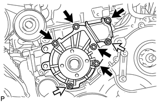

Bolt 
Nut Remove the 5 bolts, 2 nuts, engine water pump assembly and gasket.
-