WATER PUMP INSTALLATION
PROCEDURE
-
INSTALL ENGINE WATER PUMP ASSEMBLY
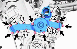

Bolt A 
Bolt B
-
Install a new gasket and the engine water pump assembly to the timing chain cover sub-assembly with the 17 bolts.
- Torque:
- for bolt A
- 21 N*m { 214 kgf*cm, 15 ft.*lbf }
- for bolt B
- 11 N*m { 112 kgf*cm, 8 ft.*lbf }
-
-
INSTALL NO. 2 IDLER PULLEY SUB-ASSEMBLY
-
w/ Idler Pulley Cover Plate:
-
Install the 2 idler pulley cover plates, 2 No. 2 idler pulleys and 2 No. 2 idler pulley cover plates with the 2 bolts.
- Torque:
- 54 N*m { 551 kgf*cm, 40 ft.*lbf }
-
-
w/o Idler Pulley Cover Plate:
-
Install the 2 No. 2 idler pulleys and 2 No. 2 idler pulley cover plates with the 2 bolts.
- Torque:
- 54 N*m { 551 kgf*cm, 40 ft.*lbf }
-
-
for Integrated Type:
-
Install the 2 No. 2 idler pulleys with the 2 bolts.
- Torque:
- 54 N*m { 551 kgf*cm, 40 ft.*lbf }
-
-
-
INSTALL V-RIBBED BELT TENSIONER ASSEMBLY
-
INSTALL WATER INLET ASSEMBLY
-
Install a new O-ring to the water outlet pipe.
-
Install a new gasket to the engine water pump assembly.
-
Apply soapy water to the O-ring.
-
Install the water inlet assembly to the timing chain cover sub-assembly with the 5 bolts.
- Torque:
- 9.0 N*m { 92 kgf*cm, 80 in.*lbf }
-
Connect the water by-pass hose, No. 2 water by-pass hose, No. 3 water by-pass hose, No. 4 water by-pass hose and No. 5 water by-pass hose to the water inlet assembly, and slide the 5 hose clamps to secure the hose.
-
Connect the radiator hose inlet and radiator hose outlet to the water inlet assembly, and slide the 2 hose clamps to secure the hose.
-
-
CONNECT COOLER COMPRESSOR ASSEMBLY
-
INSTALL GENERATOR ASSEMBLY
-
INSTALL FAN SHROUD
-
ADD ENGINE COOLANT
-
INSPECT FOR COOLANT LEAK