EXHAUST MANIFOLD INSTALLATION
PROCEDURE
-
INSTALL EXHAUST MANIFOLD
-
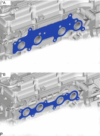
*A w/ Secondary Air Injection System *B w/o Secondary Air Injection System Install a new gasket.
-
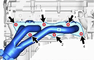
w/o Secondary Air Injection System:
Install the exhaust manifold with 6 new nuts, and tighten the nuts in the order shown in the illustration.
- Torque:
- 36 N*m { 367 kgf*cm, 27 ft.*lbf }
-
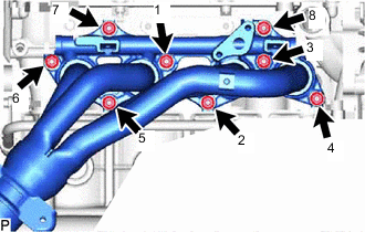
w/ Secondary Air Injection System:
Install the exhaust manifold with 8 new nuts, and tighten the nuts in the order shown in the illustration.
- Torque:
- 36 N*m { 367 kgf*cm, 27 ft.*lbf }
-
-
INSTALL MANIFOLD STAY
-
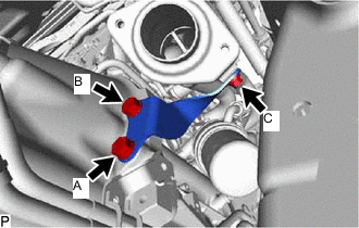
for Manual Transmission:
Install the manifold stay with the 3 bolts.
- Torque:
- for bolt A
- 71.5 N*m { 729 kgf*cm, 53 ft.*lbf }
- for bolt B
- 44 N*m { 449 kgf*cm, 32 ft.*lbf }
- for bolt C
- 30 N*m { 306 kgf*cm, 22 ft.*lbf }
-
for Automatic Transmission:
Install the manifold stay with the 3 bolts.
- Torque:
- for bolt A
- 71 N*m { 724 kgf*cm, 52 ft.*lbf }
- for bolt B
- 44 N*m { 449 kgf*cm, 32 ft.*lbf }
- for bolt C
- 30 N*m { 306 kgf*cm, 22 ft.*lbf }
-
-
INSTALL NO. 1 EXHAUST MANIFOLD HEAT INSULATOR (w/o Secondary Air Injection System)
-
Install the No. 1 exhaust manifold heat insulator with the 5 bolts.
- Torque:
- 12 N*m { 122 kgf*cm, 9 ft.*lbf }
-
-
INSTALL FRONT EXHAUST PIPE ASSEMBLY
-
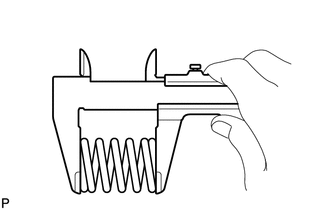
Using a vernier caliper, measure the free length of the compression spring.
Minimum free length 40 mm (1.57 in.) If the free length is less than the minimum, replace the compression spring.
-
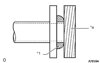
*1 Gasket *a Wooden Block Using a plastic-faced hammer and wooden block, tap on a new gasket until its surface is flush with the exhaust manifold.
Note
-
Be sure to install the gasket so that it faces the correct direction.
-
Do not reuse the gasket.
-
Do not damage the gasket.
-
When connecting the front exhaust pipe assembly, do not push in the gasket with the front exhaust pipe assembly.
-
-
Install the front exhaust pipe assembly to the No. 1 exhaust pipe support.
-
Connect the front exhaust pipe assembly to the exhaust manifold with the 2 compression springs and 2 bolts. Alternately tighten the bolts in several passes.
- Torque:
- 43 N*m { 438 kgf*cm, 32 ft.*lbf }
-
Install a new gasket and connect the front exhaust pipe assembly to the tail exhaust pipe assembly with the 2 bolts and 2 new nuts.
- Torque:
- 43 N*m { 438 kgf*cm, 32 ft.*lbf }
-
Connect the heated oxygen sensor connector and attach the wire harness clamp.
-
Connect the air fuel ratio sensor connector and attach the 3 wire harness clamps.
-
-
INSTALL AIR CLEANER CASE SUB-ASSEMBLY (w/o Secondary Air Injection System)
-
INSTALL AIR CLEANER FILTER ELEMENT SUB-ASSEMBLY (w/o Secondary Air Injection System)
-
INSTALL AIR CLEANER CAP SUB-ASSEMBLY WITH NO. 1 AIR CLEANER HOSE (w/o Secondary Air Injection System)
-
INSTALL AIR SWITCHING VALVE ASSEMBLY (w/ Secondary Air Injection System)
-
INSPECT FOR EXHAUST GAS LEAK
-
INSTALL FRONT FENDER SEAL RH