EXHAUST MANIFOLD W/ TURBOCHARGER INSTALLATION

PROCEDURE
-
TEMPORARILY INSTALL EXHAUST MANIFOLD
-
Install a new gasket and the turbocharger sub-assembly with 3 new nuts to the exhaust manifold.
- Torque:
- 52 N*m { 530 kgf*cm, 38 ft.*lbf }
-
Temporarily install the exhaust manifold with turbocharger sub-assembly and the 8 plate washers to the cylinder head sub-assembly with 8 new nuts.
-
-
INSTALL EXHAUST MANIFOLD
-
Temporarily install the turbo oil pipe sub-assembly and manifold stay.
Tech Tips
Wash the oil pipe before installing it.
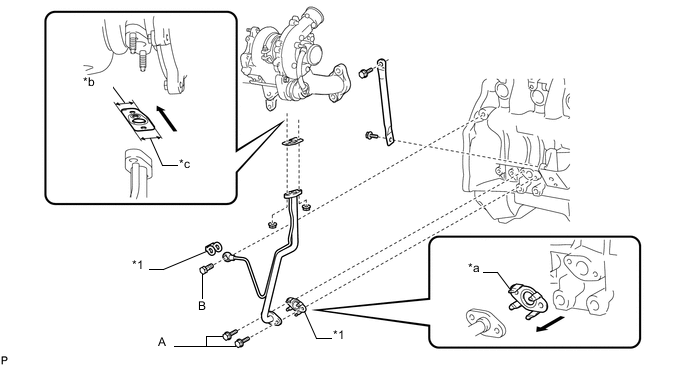
*1 Gasket - - *a Claw *b Narrow *c Wide - - 
Outside - - -
Temporarily install a new gasket and the turbo oil pipe sub-assembly with the 2 nuts, but only loosely install the nuts.
Note
The notch (wide part) of the gasket must face the engine.
-
Temporarily install a new gasket and the turbo oil pipe sub-assembly with the 2 bolts (labeled: A), but only loosely install the bolts.
Note
The claws of the gasket must face the turbo oil pipe sub-assembly.
-
Temporarily install a new gasket and the turbo oil pipe sub-assembly with the union bolt (labeled: B), but only loosely install the union bolt.
-
Temporarily install the manifold stay with the 2 bolts.
Tech Tips
The manifold stay's indented area must face the turbocharger sub-assembly.
-
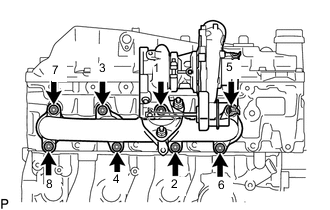
Tighten the exhaust manifold with turbocharger sub-assembly, to the cylinder head sub-assembly with 8 nuts.
- Torque:
- 40 N*m { 408 kgf*cm, 30 ft.*lbf }
Tech Tips
Tighten the nuts in the order shown in the illustration.
-
Tighten the 2 nuts and union bolt of the turbo oil inlet pipe sub-assembly, and the 2 bolts.
- Torque:
- for nut
- 13 N*m { 133 kgf*cm, 10 ft.*lbf }
- for union bolt
- 26 N*m { 265 kgf*cm, 19 ft.*lbf }
- for bolt
- 12 N*m { 122 kgf*cm, 9 ft.*lbf }
-
Tighten the 2 bolts and the manifold stay.
- Torque:
- 19 N*m { 194 kgf*cm, 14 ft.*lbf }
-
-
INSTALL TURBINE OUTLET ELBOW
-
Temporarily install the turbocharger stay to the turbine outlet elbow with the 2 bolts.
-
Temporarily install a new gasket and the turbine outlet elbow (with turbocharger stay) to the turbocharger sub-assembly with the 4 new nuts.
-
Temporarily install the turbocharger stay to the cylinder block sub-assembly with the 2 bolts.
-
Tighten the 4 nuts of the turbocharger sub-assembly.
- Torque:
- 25.5 N*m { 260 kgf*cm, 19 ft.*lbf }
-
Tighten the 4 bolts of the turbocharger stay.
- Torque:
- 38 N*m { 387 kgf*cm, 28 ft.*lbf }
-
-
INSTALL FRONT EXHAUST PIPE ASSEMBLY
-
INSTALL NO. 1 INTAKE PIPE
-
INSTALL PCV HOSE HEAT INSULATOR
-
Install the PCV hose heat insulator with the 2 bolts.
- Torque:
- 12 N*m { 122 kgf*cm, 9 ft.*lbf }
-
-
INSTALL AIR CLEANER CASE SUB-ASSEMBLY
-
Install the air cleaner case sub-assembly with the 3 bolts.
- Torque:
- 6.0 N*m { 61 kgf*cm, 53 in.*lbf }
-
Connect the 3 wire harness clamps.
-
-
INSTALL AIR CLEANER FILTER ELEMENT SUB-ASSEMBLY
-
Install the air cleaner filter element sub-assembly to the air cleaner case sub-assembly.
-
-
INSTALL AIR CLEANER CAP SUB-ASSEMBLY WITH AIR CLEANER HOSE
-
Attach the 4 clips to install the air cleaner cap sub-assembly with air cleaner hose.
-
Tighten the hose clamp.
- Torque:
- 4.0 N*m { 41 kgf*cm, 35 in.*lbf }
-
Attach the clamp and connect the intake air temperature sensor connector.
-
-
CONNECT CABLE TO NEGATIVE BATTERY TERMINAL
Note
When disconnecting the cable, some systems need to be initialized after the cable is reconnected.
-
INSPECT FOR OIL LEAK
-
INSPECT ENGINE OIL LEVEL
-
INSTALL NO. 2 ENGINE UNDER COVER
-
INSTALL NO. 1 ENGINE UNDER COVER