INTAKE MANIFOLD REMOVAL

CAUTION / NOTICE / HINT
Note
-
When replacing the parts in the following chart (A), replace the No. 1 injection pipe sub-assembly, No. 2 injection pipe sub-assembly and/or fuel inlet pipe sub-assembly with new ones.
Replaced Parts (A) Pipes Requiring New Replacement
-
Injector assembly (including shuffling the injector assemblies between the cylinders)
-
Common rail assembly
-
Cylinder head sub-assembly
-
No. 1 injection pipe sub-assembly
-
No. 2 injection pipe sub-assembly
-
Supply pump assembly
-
Common rail assembly
-
Cylinder block sub-assembly
-
Cylinder head sub-assembly
-
Cylinder head gasket
-
Timing chain case assembly
Fuel inlet pipe sub-assembly -
-
After removing the No. 1 injection pipe sub-assembly, No. 2 injection pipe sub-assembly and/or fuel inlet pipe sub-assembly, clean them with a brush and compressed air.
PROCEDURE
-
PRECAUTION
Note
After turning the ignition switch off, waiting time may be required before disconnecting the cable from the battery terminal. Therefore, make sure to read the disconnecting the cable from the battery terminal notice before proceeding with work.
-
DISCONNECT CABLE FROM NEGATIVE BATTERY TERMINAL
Note
When disconnecting the cable, some systems need to be initialized after the cable is reconnected.
-
REMOVE EGR COOLER SUB-ASSEMBLY AND NO. 2 EGR VALVE ASSEMBLY WITH ELECTRIC EGR CONTROL VALVE ASSEMBLY (w/ EGR Cooler)
-
REMOVE ELECTRIC EGR CONTROL VALVE ASSEMBLY (w/o EGR Cooler)
-
REMOVE EGR VALVE ADAPTER (w/o EGR Cooler)
CAUTION:
To prevent burns, do not touch the engine, exhaust manifold or other high temperature components while the engine is hot.
-
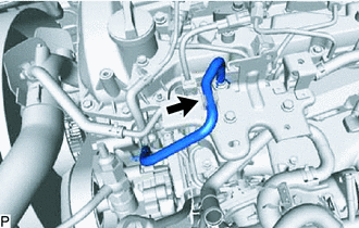
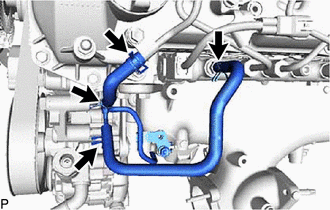
Disconnect the No. 4 fuel hose from the No. 3 water by-pass pipe sub-assembly.
-
Slide the clamp and disconnect the No. 8 water by-pass hose from the No. 3 water by-pass pipe sub-assembly.
-
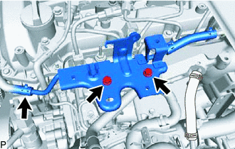
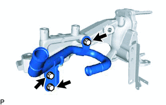
Remove the 2 bolts and No. 3 water by-pass pipe sub-assembly from the EGR valve adapter.
-
Slide the clamp and disconnect the No. 7 water by-pass hose from the EGR pipe stay.
-
Slide the clamp and disconnect the water hose from the EGR valve adapter.
-
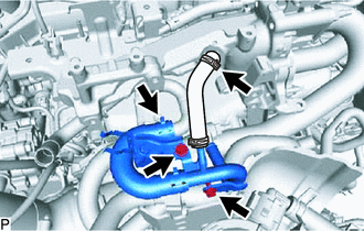
Remove the 2 bolts and disconnect the No. 4 water by-pass pipe sub-assembly from the intake manifold.
-
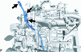
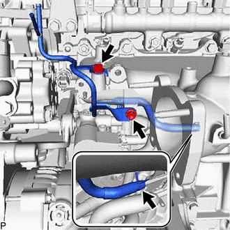
Remove the 4 nuts, bolt and No. 1 EGR pipe sub-assembly from the exhaust manifold, electric EGR control valve assembly and No. 1 vacuum transmitting pipe sub-assembly.
-
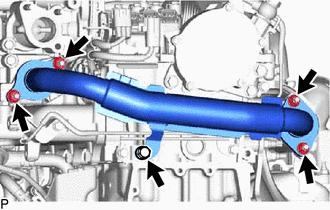
Using an E8 "TORX" socket wrench, remove the 2 stud bolts from the exhaust manifold.
-
Remove the 3 bolts and EGR pipe stay from the EGR valve adapter.
-
Remove the 3 bolts and EGR valve adapter from the intake manifold.
-
-
REMOVE ENGINE OIL LEVEL DIPSTICK GUIDE
-
Remove the engine oil level dipstick.
-
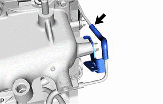
Disconnect the vacuum hose from the intake manifold.
-
Remove the bolt and engine oil level dipstick guide.
-
Remove the O-ring from the engine oil level dipstick guide.
-
-
DISCONNECT NO. 2 FUEL PIPE
-
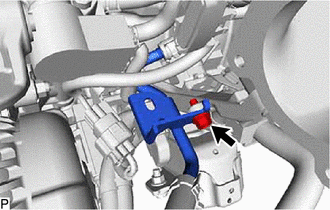
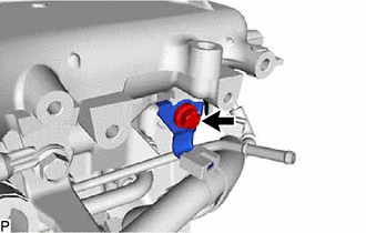
Remove the bolt and disconnect the No. 2 fuel pipe.
-
-
REMOVE WIRING HARNESS CLAMP BRACKET
-
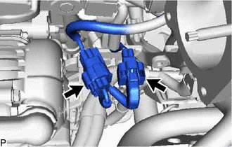
Disconnect the diesel throttle body assembly connector and pre-stroke control valve connector.
-
Detach the 2 wire harness clamps.
-
Remove the bolt and wiring harness clamp bracket.
-
-
REMOVE MANIFOLD STAY
-
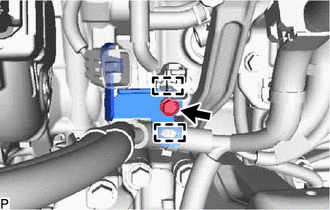
Remove the bolt and disconnect the wiring harness clamp bracket from the intake manifold stay.
-
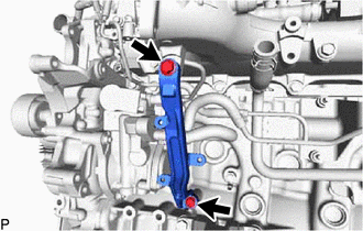
Remove the 2 bolts and manifold stay.
-
-
REMOVE NO. 3 FUEL PIPE (w/ Pressurized Fuel Filter)
-
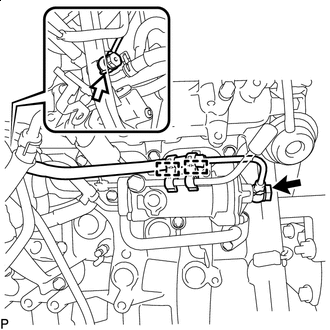

Union Bolt 
Supply Pump Hollow Screw Remove the union bolts, supply pump hollow screw and 2 gaskets from the supply pump assembly and fuel filter.
-
Remove the 2 fuel pipe clamps from the No. 3 fuel pipe and fuel filter.
Note
Do not scratch or dent the installation surface of the No. 4 fuel pipe sub-assembly.
-
-
REMOVE FUEL INLET PIPE SUB-ASSEMBLY
-
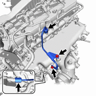
*a Common Rail Assembly Side *b Fuel Supply Pump Assembly Side Remove the 2 bolts, No. 1 injection pipe clamp and No. 2 injection pipe clamp.
-
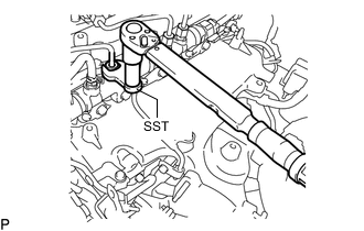
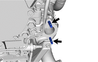
Using SST, loosen the fuel inlet pipe sub-assembly union nut of the common rail assembly side.
Note
If the No. 1 or No. 2 injection pipe clamp is removed from the inlet pipe sub-assembly, replace the No. 1 or No. 2 injection clamp with a new one.
-
Using a 19 mm union nut wrench, loosen the inlet pipe sub-assembly union nut of the fuel supply pump assembly side.
-
-
REMOVE NO. 2 NOZZLE LEAKAGE PIPE ASSEMBLY
-
Slide the clamps and remove the No. 4 fuel hose from the No. 2 nozzle leakage pipe assembly and common rail assembly.
-
Slide the 2 clamps and remove the No. 5 fuel hose from the No. 1 nozzle leakage pipe assembly and No. 2 nozzle leakage pipe assembly.
-
Slide the clamp and disconnect the No. 6 fuel hose from the No. 3 nozzle leakage pipe assembly.
-
Remove the 2 bolts and No. 2 nozzle leakage pipe assembly.
-
-
REMOVE INTAKE MANIFOLD
-
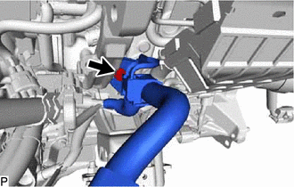
Remove the bolt and disconnect the wire harness bracket.
-
Disconnect the vacuum hose from the vacuum transmitting pipe sub-assembly.
-
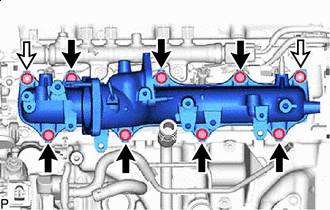
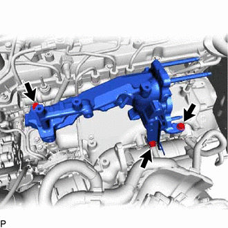
Bolt Nut Remove the 7 bolts, 2 nuts, intake manifold and gasket.
-