BRAKE MASTER CYLINDER INSTALLATION

PROCEDURE
-
INSPECT AND ADJUST BRAKE BOOSTER PUSH ROD
-
INSTALL BRAKE MASTER CYLINDER SUB-ASSEMBLY
Note
-
The master cylinder and piston are designed so that the piston can easily fall out. Prevent this by making sure the tip of the master cylinder points downward when handling the master cylinder.
-
Make sure foreign matter does not adhere to the piston of the master cylinder. If foreign matter adheres, clean it off with a cloth. Then apply lithium soap base glycol grease to the entire outer circumference contact surface area of the piston.
-
Install a new O-ring to the brake master cylinder sub-assembly.
-
Install the brake master cylinder sub-assembly and brake booster tube clamp bracket to the brake booster assembly with the 2 nuts.
- Torque:
- 12.5 N*m { 127 kgf*cm, 9 ft.*lbf }
-
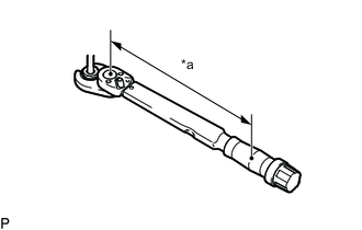
*a Torque Wrench Fulcrum Length Using a union nut wrench, connect the 2 brake lines to the brake master cylinder sub-assembly.
- Torque:
- 19.5 N*m { 199 kgf*cm, 14 ft.*lbf }
Tech Tips
-
Calculate the torque wrench reading when changing the fulcrum length of the torque wrench.
-
When using a union nut wrench (fulcrum length of 20 mm (0.7874 in.)) + torque wrench (fulcrum length of 162 mm (6.3779 in.)): 17.4 N*m (177 kgf*cm, 13 ft.*lbf)
Note
-
Do not kink or damage the brake line.
-
Do not allow any foreign matter such as dirt and dust to enter the brake line from the connecting point.
-
Connect the brake fluid level warning switch connector to the brake master cylinder sub-assembly.
-
for Manual Transmission:
Connect the clutch reservoir tube, and slide the clamp to secure it.
-
-
BLEED BRAKE SYSTEM
-
BLEED CLUTCH LINE (for Manual Transmission)