DECELERATION SENSOR(for 4WD and Pre-Runner without VSC) INSPECTION
PROCEDURE
-
INSPECT DECELERATION SENSOR
-
Connect 3 dry cell batteries of 1.5 V in series (approximately 4.5 V in total).
-
Connect the batteries' positive (+) lead to terminal 3 (VGS) and the negative (-) lead to terminal 2 (GGND).
Note
Do not apply 6 V or more to terminals 3 (VGS) and 2 (GGND).
-
Connect the voltmeter's positive (+) lead to the negative (-) lead of the batteries, and the negative (-) lead to terminal 1 (GL1).
-
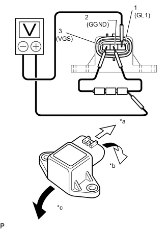
*a Front *b Forward *c Rearward Check the output voltage of terminal 1 (GL1) when the sensor is tilted forward and rearward.
Standard Voltage Tester Connection Condition Specified Condition 1 (GL1) - Battery negative (-) lead Sensor is horizontal Approx. 2.25 V 1 (GL1) - Battery negative (-) lead Sensor is tilted forward Approx. 0.45 to 2.25 V 1 (GL1) - Battery negative (-) lead Sensor is tilted rearward Approx. 2.25 to 4.05 V If the result is not as specified, replace the deceleration sensor.
Tech Tips
-
If the voltage drops, the sensor should be replaced with a new one.
-
When replacing the sensor, it should not be placed upside down.
-
-
-
CHECK DECELERATION SENSOR
-
Check the deceleration sensor.
Under any of the following conditions, replace the sensor with a new one.
-
The surface of the sensor is cracked, dented or chipped.
-
The connector is scratched, cracked or damaged.
-
The sensor has been dropped.
-
-