BRAKE ACTUATOR(w/o VSC) INSTALLATION
PROCEDURE
-
INSTALL BRAKE ACTUATOR ASSEMBLY WITH BRACKET
-
Install the brake actuator with bracket with the 3 nuts.
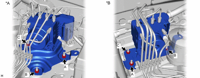
*A for LHD *B for RHD - Torque:
- 19.1 N*m { 195 kgf*cm, 14 ft.*lbf }
Note
-
Tighten the 3 nuts uniformly in alphabetical order.
-
Be careful not to damage the brake tubes.
-
Set each brake line in the correct position on the brake actuator as shown in the illustration.
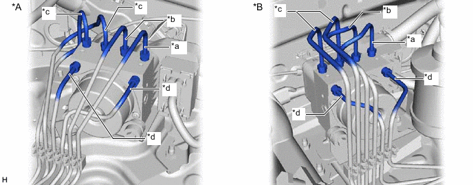
*A for LHD *B for RHD *a To Front Wheel Cylinder RH *b To Front Wheel Cylinder LH *c To Rear Wheel Cylinder *d From Master Cylinder -
Using a union nut wrench, connect the 6 brake lines to the correct locations on the actuator as shown in the illustration.
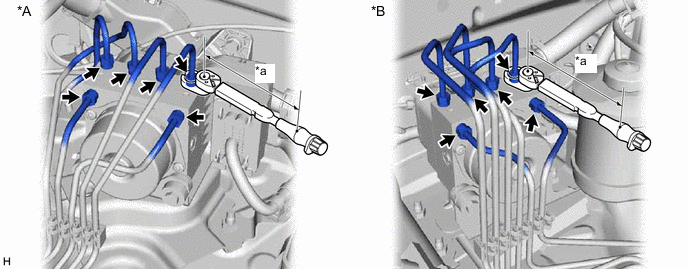
*A for LHD *B for RHD *a Torque Wrench Fulcrum Length - - - Torque:
- Specified tightening torque
- 15.2 N*m { 155 kgf*cm, 11 ft.*lbf }
Tech Tips
-
Calculate the torque wrench reading when changing the fulcrum length of the torque wrench.
-
When using a union nut wrench (fulcrum length of 22 mm (0.8661 in.)) + torque wrench (fulcrum length of 162 mm (6.3779 in.)): 13.4 N*m (137 kgf*cm, 10 ft.*lbf)
-
Attach the clamp to the brake actuator bracket.
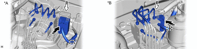
*A for LHD *B for RHD 
Connector Connected 
Lock Lever Locked -
Connect the connector to the brake actuator assembly and lock the lock lever.
Note
-
Make sure that the connector is locked securely.
-
Make sure that the actuator connector can be connected smoothly. Do not allow water, oil or dirt to enter the connector.
-
-
-
CONNECT CABLE TO NEGATIVE BATTERY TERMINAL
Note
When disconnecting the cable, some systems need to be initialized after the cable is reconnected.
-
BLEED BRAKE SYSTEM
-
SENSOR CHECK USING TEST MODE (SIGNAL CHECK)
Note
After replacing the skid control ECU (brake actuator assembly), it is necessary to perform registration of rear differential lock identification information. Rear differential lock identification information is automatically acquired when the system enters test mode.
-
CHECK BRAKE ACTUATOR WITH GTS