BRAKE ACTUATOR(w/ VSC) INSTALLATION
PROCEDURE
-
INSTALL BRAKE ACTUATOR ASSEMBLY
-
Install the brake actuator with bracket with the 3 nuts.
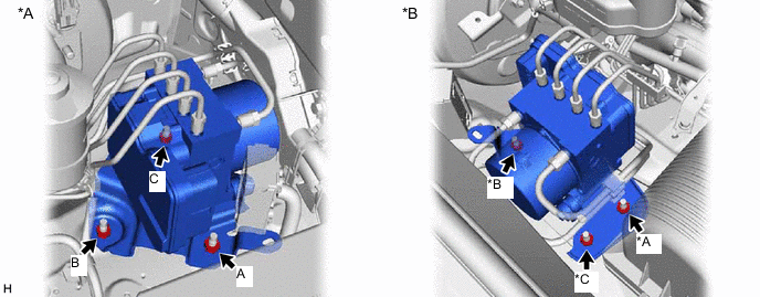
*A for LHD *B for RHD - Torque:
- 19.1 N*m { 195 kgf*cm, 14 ft.*lbf }
Note
-
Tighten the 3 nuts uniformly in alphabetical order.
-
Be careful not to damage the brake tubes.
-
Do not drop the actuator. If dropped, replace it.
-
Set each brake line in the correct position on the brake actuator as shown in the illustration.
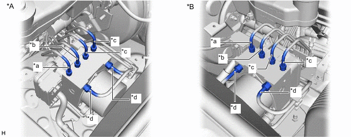
*A for LHD *B for RHD *a To Front Wheel Cylinder RH *b To Front Wheel Cylinder LH *c To Rear Wheel Cylinder *d From Master Cylinder -
Temporarily install the 6 brake lines to the correct position on the brake actuator assembly as shown in the illustration.
-
Using a union nut wrench, tighten each brake line.
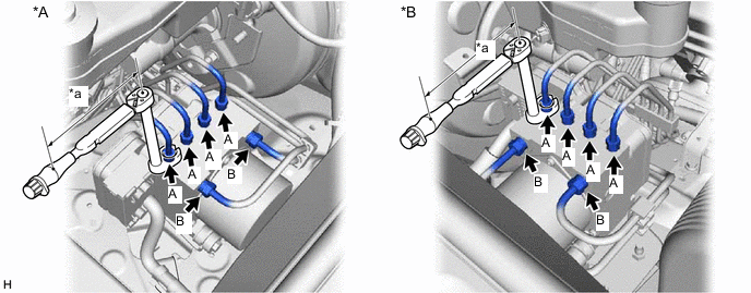
*A for LHD *B for RHD *a Torque Wrench Fulcrum Length - - Specified tightening torque for flare nut A 15.2 N*m (155 kgf*cm, 11 ft.*lbf) for flare nut B 19.5 N*m (199 kgf*cm, 14 ft.*lbf) Tech Tips
-
Calculate the torque wrench reading when changing the fulcrum length of the torque wrench.
-
for flare nut A
When using a union nut wrench (fulcrum length of 22 mm (0.8661 in.)) + torque wrench (fulcrum length of 162 mm (6.3779 in.)): 13.4 N*m (137 kgf*cm, 10 ft.*lbf).
-
for flare nut B
When using a union nut wrench (fulcrum length of 22 mm (0.8661 in.)) + torque wrench (fulcrum length of 162 mm (6.3779 in.)): 17.2 N*m (175 kgf*cm, 13 ft.*lbf)
-
-
Connect the connector to the brake actuator assembly and lock the lock lever.
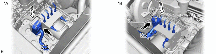
*A for LHD *B for RHD 
Connector Connected 
Lock Lever Locked Note
-
Make sure that the connector is locked securely.
-
Make sure that the actuator connector can be connected smoothly. Do not allow water, oil or dirt to enter the connector.
-
-
Attach the clamp to the brake actuator bracket assembly.
-
-
BLEED BRAKE SYSTEM
-
CONNECT CABLE TO NEGATIVE BATTERY TERMINAL
Note
When disconnecting the cable, some systems need to be initialized after the cable is reconnected.
-
INSTALL YAW RATE AND ACCELERATION SENSOR ZERO POINT CALIBRATION AND STORE SYSTEM INFORMATION
-
CHECK BRAKE ACTUATOR WITH GTS