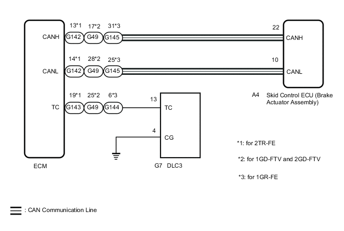
VEHICLE STABILITY CONTROL SYSTEM TC and CG Terminal Circuit
DESCRIPTION
Connecting terminals TC and CG of the DLC3 causes the ECU to display the DTC by blinking the ABS warning light and slip indicator light.
WIRING DIAGRAM
CAUTION / NOTICE / HINT
Note
When replacing the skid control ECU (brake actuator assembly), perform zero point calibration and store system information.
PROCEDURE
-
CHECK CAN COMMUNICATION SYSTEM
-
Check if CAN communication system DTCs are output.
for LHD: Click here
for RHD: Click here
Result Proceed to DTC is not output DTC is output
DTC is output 
CHECK CAN COMMUNICATION SYSTEM for LHD: Click here
CHECK CAN COMMUNICATION SYSTEM for RHD: Click hereDTC is not output 
-
-
INSPECT DLC3
-
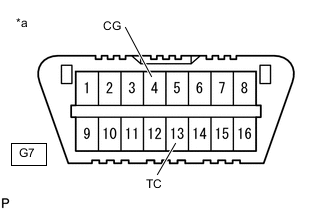
*a Front view of DLC3 Turn the ignition switch to ON.
-
Measure the voltage according to the value(s) in the table below.
Standard Voltage Tester Connection Switch Condition Specified Condition G7-13 (TC) - G7-4 (CG) Ignition switch ON 11 to 14 V Result Proceed to OK NG
NG 
CHECK HARNESS AND CONNECTOR (TC of DLC3 - ECM) Click here
OK
-
-
REPLACE ECM
-
*a Front view of DLC3 Turn the ignition switch off.
-
Replace the ECM.
for 1GD-FTV: Click here
for 1GR-FE: Click here
for 2GD-FTV: Click here
for 2TR-FE: Click here
-
Using SST, connect terminals 13 (TC) and 4 (CG) of the DLC3.
- SST
- 09843-18040
-
Check that the ABS warning and slip indicator light are blinking.
OK The ABS warning and slip indicator light are blinking. Result Proceed to OK NG
OK
END
NG
REPLACE BRAKE ACTUATOR ASSEMBLY Click here
-
-
CHECK HARNESS AND CONNECTOR (TC of DLC3 - ECM)
-
Turn the ignition switch off.
-
Disconnect the G143*1, G49*2 or G144*3 ECM connector.
-
*1: for 2TR-FE
-
*2: for 1GD-FTV and 2GD-FTV
-
*3: for 1GR-FE
-
-
Measure the resistance according to the value(s) in the table below.
Standard Resistance for 2TR-FE: Tester Connection Condition Specified Condition G7-13 (TC) - G143-19 (TC) Always Below 1 Ω G7-13 (TC) or G143-19 (TC) - Body ground Always 10 kΩ or higher for 1GD-FTV and 2GD-FTV: Tester Connection Condition Specified Condition G7-13 (TC) - G49-25 (TC) Always Below 1 Ω G7-13 (TC) or G49-25 (TC) - Body ground Always 10 kΩ or higher for 1GR-FE: Tester Connection Condition Specified Condition G7-13 (TC) - G144-6 (TC) Always Below 1 Ω G7-13 (TC) or G144-6 (TC) - Body ground Always 10 kΩ or higher Result Proceed to OK NG
NG
REPAIR OR REPLACE HARNESS OR CONNECTOR
OK
-
-
CHECK HARNESS AND CONNECTOR (CG of DLC3 - BODY GROUND)
-
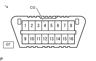
*a Front view of DLC3 Measure the resistance according to the value(s) in the table below.
Standard Resistance Tester Connection Condition Specified Condition G7-4 (CG) - Body ground Always Below 1 Ω Result Proceed to OK NG
NG
REPAIR OR REPLACE HARNESS OR CONNECTOR
OK
-
-
REPLACE ECM
-
*a Front view of DLC3 Replace the ECM.
for 1GD-FTV: Click here
for 1GR-FE: Click here
for 2GD-FTV: Click here
for 2TR-FE: Click here
-
Using SST, connect terminals 13 (TC) and 4 (CG) of the DLC3.
- SST
- 09843-18040
-
Check that the ABS warning and slip indicator light are blinking.
OK The ABS warning and slip indicator light are blinking. Result Proceed to OK NG
OK
END
NG
REPLACE BRAKE ACTUATOR ASSEMBLY Click here
-