VEHICLE STABILITY CONTROL SYSTEM TERMINALS OF ECU

-
TERMINALS OF ECU
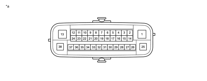
*a Component without harness connected
(Skid Control ECU [Brake Actuator Assembly])
- - Terminal No. (Symbol) Terminal Description 1 (GND2) Pump motor ground 2 - (Not used) 3 (EXI)*3 A.D.D. position switch (Differential motor actuator assembly) signal input 4 - (Not used) 5 (EXI4)*3 L4 detection switch (Transfer shift actuator assembly) input 6 - (Not used) 7 (STP2) Stop light switch assembly input 8 - (Not used) 9 - (Not used) 10 (CANL) CAN communication line L 11 - (Not used) 12 (IG1) ECU power supply input 13 (BM) Motor relay power supply 14 (SP1) Speed signal output for speedometer 15 (RR-) Rear wheel speed RH (-) signal input 16 (RR+) Rear wheel speed RH (+) power supply output 17 (FL-) Front wheel speed LH (-) signal input 18 (FL+) Front wheel speed LH (+) power supply output 19 - (Not used) 20 (TMVC)*1, *2 Neutral position switch power supply 21 (TME2)*1, *2 Neutral position switch signal input 22 (CANH) CAN communication line H 23 - (Not used) 24 (TS) Sensor check input 25 (GND1) Skid control ECU (Brake actuator assembly) ground 26 (STPO) Stop light switch assembly output 27 (HDCS)*1 Downhill assist control switch input 28 (RL-) Rear wheel speed LH (-) signal input 29 (RL+) Rear wheel speed LH (+) power supply output 30 (FR-) Front wheel speed RH (-) signal input 31 (FR+) Front wheel speed RH (+) power supply output 32 (TMN)*1, *2 Neutral position switch signal output 33 (CSW) VSC OFF switch input 34 - (Not used) 35 (STP) Stop light switch assembly input 36 - (Not used) 37 - (Not used) 38 (+BS) Solenoid relay power supply
-
*1: w/ Downhill Assist Control
-
*2: for Manual Transmission
-
*3: for 4WD
-
-
TERMINAL INSPECTION
-
Disconnect the A4 connector and measure the voltage or resistance on the wire harness side.
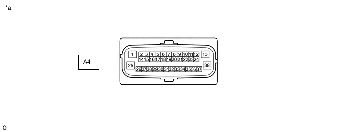
*a Front view of wire harness connector
(to Skid Control ECU [Brake Actuator Assembly])
- - Tech Tips
Voltage cannot be measured with the connector connected to the skid control (brake actuator assembly) as the connector is watertight.
Terminal No. (Symbol) Wiring Color Terminal Description Condition Specified Condition A4-1 (GND2) - Body ground W-B - Body ground Pump motor ground Always Below 1 Ω A4-3 (EXI) - Body ground*3 W - Body ground*4 A.D.D. position switch (Differential motor actuator assembly) signal input
-
Ignition switch ON
-
4WD control switch (Transfer position switch) set to H2
11 to 14 V L - Body ground*5 A4-5 (EXI4) - Body ground*3 G - Body ground*4 L4 detection switch (Transfer shift actuator assembly) input
-
Ignition switch ON
-
4WD control switch (Transfer position switch) not set to L4
11 to 14 V SB - Body ground*5 A4-7 (STP2) - Body ground L - Body ground Stop light switch assembly input Stop light switch assembly on → off
(Brake pedal depressed → released)
8 to 14 V → Below 1.5 V A4-12 (IG1) - Body ground L - Body ground*4 ECU power supply input Ignition switch ON 11 to 14 V V - Body ground*5 A4-13 (BM) - Body ground R - Body ground Motor relay power supply Always 11 to 14 V A4-14 (SP1) - Body ground Y - Body ground Speed signal output for speedometer Ignition switch ON 11 to 14 V A4-20 (TMVC) - Body ground*1, *2 B - Body ground Neutral position switch power supply
-
Ignition switch ON
-
Engine stopped
4.5 to 5.5 V A4-25 (GND1) - Body ground W-B - Body ground Skid control ECU (Brake actuator assembly) ground Always Below 1 Ω A4-26 (STPO) - Body ground P - Body ground Stop light switch assembly output Ignition switch ON 11 to 14 V A4-27 (HDCS) - Body ground*1 SB - Body ground Downhill assist control switch input Downhill assist control switch on → off Below 1 Ω → 10 kΩ or higher A4-32 (TMN) - A4-21 (TME2)*1, *2 P - R Neutral position switch signal
-
Ignition switch ON
-
Shift lever in neutral
2.7 to 4.3 V
-
Ignition switch ON
-
Shift lever in any other than neutral
0.7 to 1.9 V A4-33 (CSW) - Body ground GR - Body ground VSC OFF switch input VSC OFF switch pressed and held → released Below 1 Ω → 10 kΩ or higher A4-35 (STP) - Body ground L - Body ground Stop light switch assembly input Stop light switch assembly on → off
(Brake pedal depressed → released)
8 to 14 V → Below 1.5 V A4-38 (+BS) - Body ground B - Body ground Solenoid relay power supply Always 11 to 14 V
-
*1: w/ Downhill Assist Control
-
*2: for Manual Transmission
-
*3: for 4WD
-
*4: for 1GD-FTV RHD and 2GD-FTV RHD
-
*5: except 1GD-FTV RHD and 2GD-FTV RHD
-
-