ANTI-LOCK BRAKE SYSTEM, Diagnostic DTC:C1243, C1245, C1279, C1418

| DTC Code | DTC Name |
|---|---|
| C1243 | Deceleration Sensor |
| C1245 | Malfunction in Deceleration Sensor |
| C1279 | Abnormal Output Voltage in Deceleration Sensor (Test Mode DTC) |
| C1418 | Open or Short in Deceleration Sensor |
DESCRIPTION
The skid control ECU (brake actuator assembly) receives signals from the deceleration sensor. If the sensor functions abnormally, the ABS warning light turns on.
| DTC No. | Detection Item | DTC Detection Condition | Trouble Area |
|---|---|---|---|
| C1243 | Deceleration Sensor | While vehicle speed decreases from 30 km/h (19 mph) to 0 km/h (0 mph), sensor signal does not change 16 times or more. |
|
| C1245 | Malfunction in Deceleration Sensor | At vehicle speed of 30 km/h (19 mph) or more, difference between back and forth G value calculated using G sensor signals and back and forth G value calculated using vehicle speed, exceeds 0.35 G for 60 seconds or more. |
|
| C1279 | Abnormal Output Voltage in Deceleration Sensor (Test Mode DTC) | Detected only during Test Mode. |
|
| C1418 | Open or Short in Deceleration Sensor | One of the following conditions is met when the voltage at terminal IG1 is 9.5 V or higher:
|
|
WIRING DIAGRAM
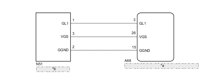
| *a | Skid Control ECU (Brake Actuator Assembly) |
| *b | Deceleration Sensor |
CAUTION / NOTICE / HINT
Note
When replacing the skid control ECU (brake actuator assembly), perform Test Mode (Signal Check) to acquire the rear differential lock identification information.
PROCEDURE
-
CHECK DECELERATION SENSOR INSTALLATION
-
Check that the deceleration sensor is installed properly.
OK The sensor should be tightened to the specified torque. The sensor is not installed in a tilted position. Result Result Proceed to The sensor is tightened to the specified torque and the sensor is not tilted. A The sensor is not tightened to the specified torque or the sensor is tilted. B
B 
DECELERATION SENSOR INSTALLATION Click here
A 
-
-
READ VALUE USING GTS (DECELERATION SENSOR)
-
Connect the GTS to the DLC3.
-
Turn the ignition switch to ON.
-
Turn the GTS on.
-
Enter the following menus: Chassis / ABS/VSC/TRC / Data List.
-
According to the display on the GTS, read the Data List.
Chassis > ABS/VSC/TRC > Data ListTester Display Measurement Item Range Normal Condition Diagnostic Note Deceleration Sensor Deceleration sensor reading Min.: -18.525 m/s2, Max.: 18.387 m/s2
- During deceleration/acceleration:
Changes continuously
Chassis > ABS/VSC/TRC > Data ListTester Display Deceleration Sensor -
Check that the deceleration value of the deceleration sensor displayed on the GTS changes when the vehicle is tilted.
OK Deceleration value changes. Result Proceed to OK NG
NG 
INSPECT DECELERATION SENSOR Click here
OK
-
-
RECONFIRM DTC
-
Clear the DTC.
Chassis > ABS/VSC/TRC > Clear DTCs -
Turn the ignition switch off.
-
Drive the vehicle at a speed of 30 km/h (19 mph) or more for at least 60 seconds or more.
-
Check if the same DTCs are recorded.
Chassis > ABS/VSC/TRC > Trouble CodesResult Proceed to DTC is output DTC is not output
DTC is output
REPLACE BRAKE ACTUATOR ASSEMBLY Click here
DTC is not output
USE SIMULATION METHOD TO CHECK Click here
-
-
INSPECT DECELERATION SENSOR
-
Turn the ignition switch off.
-
Remove the deceleration sensor.
-
Inspect the deceleration sensor.
OK The deceleration sensor is normal. Result Proceed to OK NG
NG
REPLACE DECELERATION SENSOR Click here
OK
-
-
CHECK HARNESS AND CONNECTOR (BRAKE ACTUATOR ASSEMBLY - DECELERATION SENSOR)
-
Disconnect the A68 skid control ECU (brake actuator assembly) connector.
-
Measure the resistance according to the value(s) in the table below.
Standard Resistance Tester Connection Condition Specified Condition A68-3 (GL1) - N51-1 (GL1) Always Below 1 Ω A68-26 (VGS) - N51-3 (VGS) Always Below 1 Ω A68-15 (GGND) - N51-2 (GGND) Always Below 1 Ω A68-3 (GL1) or N51-1 (GL1) - Body ground Always 10 kΩ or higher A68-26 (VGS) or N51-3 (VGS) - Body ground Always 10 kΩ or higher A68-15 (GGND) or N51-2 (GGND) - Body ground Always 10 kΩ or higher Result Proceed to OK NG
OK
REPLACE BRAKE ACTUATOR ASSEMBLY Click here
NG
REPAIR OR REPLACE HARNESS OR CONNECTOR
-