TIRE PRESSURE WARNING SYSTEM, Diagnostic DTC:C2174/74, C2191/91
| DTC Code | DTC Name |
|---|---|
| C2174/74 | Vehicle Speed Signal Malfunction |
| C2191/91 | Vehicle Speed Signal Error (Test Mode DTC) |
DESCRIPTION
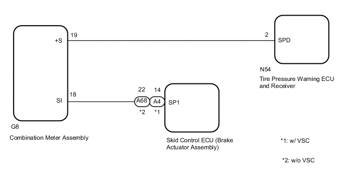
Speeds signals are sent from the combination meter assembly to the tire pressure warning ECU and receiver.
DTC C2191/91 is stored only during the signal check.
| DTC No. | Detection Item | DTC Detection Condition | Trouble Area |
|---|---|---|---|
| C2174/74 | Vehicle Speed Signal Malfunction | All conditions below are met:
|
|
| C2191/91 | Vehicle Speed Signal Error (Test Mode DTC) | Test mode procedure is performed. |
|
WIRING DIAGRAM
CAUTION / NOTICE / HINT
Note
-
When replacing the tire pressure warning ECU and receiver, read the transmitter IDs stored in the old ECU using the GTS and write them down before removal.
-
It is necessary to perform initialization after registration Click here of the transmitter IDs into the tire pressure warning ECU and receiver if the ECU has been replaced.
Tech Tips
When the speedometer needle is not moving, first troubleshoot the meter/gauge system.
PROCEDURE
-
READ VALUE USING DATA LIST (VEHICLE SPEED)
-
Turn the ignition switch off.
-
Connect the GTS to the DLC3.
-
Turn the ignition switch to ON.
-
Turn the GTS on.
-
Enter the following menus: Chassis / Tire Pressure Monitor / Data List.
Chassis > Tire Pressure Monitor > Data ListTester Display Measurement Item Range Normal Condition Diagnostic Note Vehicle Speed Vehicle speed reading min.: 0 km/h (0 mph), max.: 255 km/h (158 mph) Actual vehicle speed Speed indicated on the combination meter assembly
Chassis > Tire Pressure Monitor > Data ListTester Display Vehicle Speed -
Check that the values indicated on the GTS and on the combination meter assembly are the same.
OK Vehicle speed indicated on the GTS indicates the actual speed. Result Proceed to OK NG
NG 
CHECK HARNESS AND CONNECTOR (TIRE PRESSURE WARNING ECU AND RECEIVER - COMBINATION METER ASSEMBLY) Click here
OK 
-
-
CHECK DTC OUTPUT
-
Clear the DTCs.
Chassis > Tire Pressure Monitor > Clear DTCs -
Turn the ignition switch off.
-
Turn the ignition switch to ON.
-
Perform a driving test.
-
Check for DTCs.
Chassis > Tire Pressure Monitor > Trouble CodesTech Tips
The time required for DTC C2174 to be stored is 20 minutes.
Result Result Proceed to DTC C2174 is not output A DTC C2174 is output B
A 
USE SIMULATION METHOD TO CHECK Click here
B
GO TO STEP 6 Click here
-
-
CHECK HARNESS AND CONNECTOR (TIRE PRESSURE WARNING ECU AND RECEIVER - COMBINATION METER ASSEMBLY)
-
Turn the ignition switch off.
-
Disconnect the N54 tire pressure warning ECU and receiver connector.
-
Disconnect the G8 combination meter assembly connector.
-
Measure the resistance according to the value(s) in the table below.
Standard Resistance Tester Connection Condition Specified Condition N54-2 (SPD) - G8-19 (+S) Always Below 1 Ω N54-2 (SPD) or G8-19 (+S) - Body ground Always 10 kΩ or higher Result Proceed to OK NG
NG
REPAIR OR REPLACE HARNESS OR CONNECTOR
OK
-
-
CHECK HARNESS AND CONNECTOR (COMBINATION METER ASSEMBLY - BRAKE ACTUATOR ASSEMBLY OR SPEEDOMETER SENSOR)
-
w/o VSC:
Disconnect the A68 skid control ECU (brake actuator assembly) connector.
w/ VSC:
Disconnect the A4 skid control ECU (brake actuator assembly) connector.
-
Disconnect the G8 combination meter assembly connector.
-
Measure the resistance according to the value(s) in the table below.
Standard Resistance w/o VSC: Tester Connection Condition Specified Condition A68-22 (SP1) - G8-18 (SI) Always Below 1 Ω A68-22 (SP1) or G8-18 (SI) - Body ground Always 10 kΩ or higher w/ VSC: Tester Connection Condition Specified Condition A4-14 (SP1) - G8-18 (SI) Always Below 1 Ω A4-14 (SP1) or G8-18 (SI) - Body ground Always 10 kΩ or higher Result Proceed to OK NG
NG
REPAIR OR REPLACE HARNESS OR CONNECTOR
OK
-
-
CHECK DTC OUTPUT (ENGINE CONTROL SYSTEM)
-
Clear the DTCs.
-
for 1GR-FE: Click here
-
for 2TR-FE: Click here
-
for 2GD-FTV: Click here
-
for 2GD-FTV (w/o EGR Cooler): Click here
-
for 1GD-FTV: Click here
-
for 1GD-FTV (w/ DPF): Click here
-
for 1GD-FTV (w/o EGR System): Click here
-
for 1GD-FTV (w/o EGR Cooler): Click here
Powertrain > Engine and ECT > Clear DTCs -
-
Turn the ignition switch off.
-
Turn the ignition switch to ON.
-
Check for DTCs.
-
for 1GR-FE: Click here
-
for 2TR-FE: Click here
-
for 2GD-FTV: Click here
-
for 2GD-FTV (w/o EGR Cooler): Click here
-
for 1GD-FTV: Click here
-
for 1GD-FTV (w/ DPF): Click here
-
for 1GD-FTV (w/o EGR System): Click here
-
for 1GD-FTV (w/o EGR Cooler): Click here
Powertrain > Engine and ECT > Trouble CodesResult Result Proceed to DTC P0500 is not output A DTC P0500 is output B -
B
GO TO METER / GAUGE SYSTEM Click here
A
-
-
REPLACE TIRE PRESSURE WARNING ECU AND RECEIVER
-
Replace the tire pressure warning ECU and receiver.
Result Proceed to NEXT
NEXT
-
-
REGISTRATION OF TRANSMITTER ID
-
Perform registration.
Result Proceed to NEXT
NEXT
-
-
PERFORM INITIALIZATION
-
Set the tire pressure to the specified value.
-
Perform initialization.
Result Proceed to NEXT
NEXT
-
-
CHECK TEST MODE DTC (C2191/91)
-
Turn the ignition switch off.
-
Connect the GTS to the DLC3.
-
Turn the ignition switch to ON.
-
Turn the GTS on.
-
Enter the following menus: Chassis / Tire Pressure Monitor / Utility / Signal Check.
Chassis > Tire Pressure Monitor > UtilityTester Display Signal Check -
Drive the vehicle at 20 km/h (12 mph) or more for 3 seconds or more to check the vehicle speed signal (C2191/91).
Result Result Proceed to DTC C2191 is not cleared A DTC C2191 is cleared B
A
GO TO DTC C2121/21 TO C2125/25 Click here
B
END
-