FRONT UPPER SUSPENSION ARM INSTALLATION

CAUTION / NOTICE / HINT
Tech Tips
-
Use the same procedure for the RH and LH sides.
-
The procedure listed below is for the LH side.
PROCEDURE
-
INSTALL FRONT UPPER BALL JOINT
-
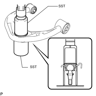
Using SST and a press, press in a new front upper ball joint.
- SST
- 09612-30012
- 09223-00010
-
Using a snap ring expander, install a new snap ring.
Note
Make sure the snap ring is securely installed in the groove.
-
-
INSTALL UPPER BALL JOINT DUST COVER
-
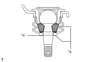
*a MP grease Pack the upper arm ball joint with MP grease.
Grease capacity 8.0 g (0.282 oz.) -
Apply MP grease to the locations shown in the illustration.
Note
Do not apply MP grease to the tapered or threaded parts of the ball joint.
-
Install a new upper ball joint dust cover to the front upper suspension arm assembly LH.
-
Install a new dust cover set ring.
-
-
INSTALL FRONT UPPER SUSPENSION ARM BUSH LH
-
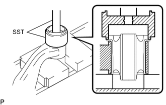
Using SST and a press, press in a new front upper suspension arm bush LH.
- SST
- 09316-10010
- 09950-70010 ( 09951-07100 )
-
-
TEMPORARILY INSTALL FRONT UPPER SUSPENSION ARM ASSEMBLY LH
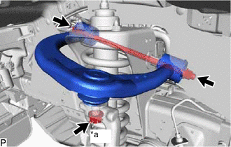
*a Nut
-
Temporarily install the front upper suspension arm assembly LH and 2 retainers with the bolt and nut.
Tech Tips
Fix the nut in place and temporarily install the bolt.
-
Install the front upper suspension arm assembly LH to the steering knuckle with the nut.
- Torque:
- 110 N*m { 1122 kgf*cm, 81 ft.*lbf }
-
Install a new clip.
-
-
CONNECT FRONT STABILIZER LINK ASSEMBLY LH
-
Connect the front stabilizer link assembly LH to the steering knuckle with the nut.
- Torque:
- 94 N*m { 959 kgf*cm, 69 ft.*lbf }
Tech Tips
If the ball joint turns together with the nut, use a 6 mm hexagon wrench to hold the stud in place.
-
-
CONNECT FRONT SPEED SENSOR LH
-
Install the 2 bolts and connect the front speed sensor LH.
- Torque:
- 32 N*m { 326 kgf*cm, 24 ft.*lbf }
-
-
INSTALL FRONT WHEEL
-
STABILIZE SUSPENSION
-
TIGHTEN FRONT UPPER SUSPENSION ARM ASSEMBLY LH
-
Tighten the bolt of the front upper suspension arm assembly LH.
- Torque:
- 115 N*m { 1173 kgf*cm, 85 ft.*lbf }
Note
Do not tighten the bolt.
-
-
INSPECT AND ADJUST FRONT WHEEL ALIGNMENT
-
PERFORM INITIALIZATION (w/ Automatic Headlight Beam Level Control System)
-
INSPECT AUTOMATIC LIGHT CONTROL SYSTEM (w/ Automatic Headlight Beam Level Control System)
-
INSPECT HEADLIGHT AIMING (w/ Automatic Headlight Beam Level Control System)