FRONT WHEEL ALIGNMENT ADJUSTMENT

CAUTION / NOTICE / HINT
The necessary procedures (adjustment, calibration, initialization, or registration) that must be performed after parts are removed, installed, or replaced during the front wheel alignment adjustment removal /installation are shown below.
| Replacement Part or Procedure | Necessary Procedures | Effects/Inoperative when not Performed | Link |
|---|---|---|---|
| Front wheel alignment adjustment |
|
VSC disable or malfunctioning |
PROCEDURE
-
INSPECT TIRES
-
INSPECT VEHICLE HEIGHT
Note
Before inspecting the wheel alignment, adjust the vehicle height to the specification.
-
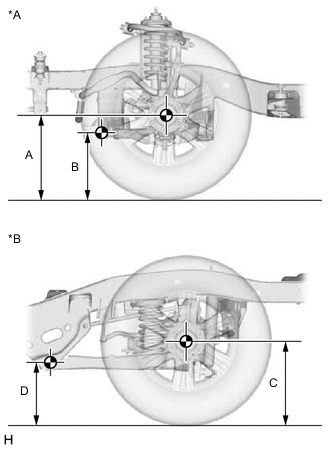
*A for Front *B for Rear Press down on the vehicle several times to stabilize the suspension, and measure the vehicle height.
Standard Vehicle Height (for Unloaded Vehicle) Vehicle Model Front A - B Rear C - D GUN156R-STFLHQ Tire Size 265/65R17
for Steel Wheel
70 mm (2.76 in.) 72 mm (2.83 in.) Tire Size 265/65R17
for Aluminum Wheel
70 mm (2.76 in.) 71 mm (2.80 in.) GUN156R-STFSHQ 70 mm (2.76 in.) 72 mm (2.83 in.) GUN156R-STFMHQ 71 mm (2.80 in.) 72 mm (2.83 in.) GUN156R-STTLHQ Tire Size 265/65R17
for Steel Wheel
70 mm (2.76 in.) 72 mm (2.83 in.) Tire Size 265/65R17
for Aluminum Wheel
70 mm (2.76 in.) 71 mm (2.80 in.) GUN156R-STTSHQ 70 mm (2.76 in.) 71 mm (2.80 in.) GUN156R-STTMHQ 71 mm (2.80 in.) 72 mm (2.83 in.) Measuring point A Ground clearance of front wheel center B Ground clearance of lower suspension arm No. 2 set bolt center C Ground clearance of rear wheel center D Ground clearance of strut rod set bolt center If the vehicle height is not as specified, press down on the vehicle several times to stabilize the suspension. Then measure the vehicle height again.
Note
The standard value shown above is a value that is used for adjusting the wheel alignment and does not indicate the height of an actual vehicle.
-
-
INSPECT CAMBER, CASTER AND STEERING AXIS INCLINATION
-
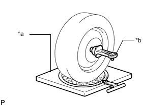
*a Gauge *b Alignment Tester Install a camber-caster-kingpin gauge or place the front wheels on the center of a wheel alignment tester.
-
Inspect the camber, caster and steering axis inclination.
Standard Camber Inclination (for Unloaded Vehicle) Vehicle Model Camber Inclination GUN156R-STFLHQ
Right-left error
Tire Size 265/65R17
for Steel Wheel
0°17' +/-30' (0.28° +/-0.50°)
30' (0.50°) or less
Tire Size 265/65R17
for Aluminum Wheel
0°18' +/-30' (0.30° +/-0.50°)
30' (0.50°) or less
GUN156R-STFSHQ
Right-left error
0°17' +/-30' (0.28° +/-0.50°)
30' (0.50°) or less
GUN156R-STFMHQ
Right-left error
Tire Size 265/60R18 0°16' +/-30' (0.27° +/-0.50°)
30' (0.50°) or less
Tire Size 265/65R17 0°17' +/-30' (0.28° +/-0.50°)
30' (0.50°) or less
GUN156R-STTLHQ
Right-left error
Tire Size 265/65R17
for Steel Wheel
0°17' +/-30' (0.28° +/-0.50°)
30' (0.50°) or less
Tire Size 265/65R17
for Aluminum Wheel
0°18' +/-30' (0.30° +/-0.50°)
30' (0.50°) or less
GUN156R-STTSHQ
Right-left error
0°18' +/-30' (0.30° +/-0.50°)
30' (0.50°) or less
GUN156R-STTMHQ
Right-left error
Tire Size 265/60R18 0°16' +/-30' (0.27° +/-0.50°)
30' (0.50°) or less
Tire Size 265/65R17 0°17' +/-30' (0.28° +/-0.50°)
30' (0.50°) or less
Standard Caster Inclination (for Unloaded Vehicle) Vehicle Model Caster Inclination GUN156R-STFLHQ
Right-left error
Tire Size 265/65R17
for Steel Wheel
2°38' +/-30' (2.63° +/-0.50°)
30' (0.50°) or less
Tire Size 265/65R17
for Aluminum Wheel
2°36' +/-30' (2.60° +/-0.50°)
30' (0.50°) or less
GUN156R-STFSHQ
Right-left error
2°36' +/-30' (2.60° +/-0.50°)
30' (0.50°) or less
GUN156R-STFMHQ
Right-left error
Tire Size 265/60R18 2°38' +/-30' (2.63° +/-0.50°)
30' (0.50°) or less
Tire Size 265/65R17 2°37' +/-30' (2.62° +/-0.50°)
30' (0.50°) or less
GUN156R-STTLHQ
Right-left error
2°36' +/-30' (2.60° +/-0.50°)
30' (0.50°) or less
GUN156R-STTSHQ
Right-left error
2°36' +/-30' (2.60° +/-0.50°)
30' (0.50°) or less
GUN156R-STTMHQ
Right-left error
Tire Size 265/60R18 2°38' +/-30' (2.63° +/-0.50°)
30' (0.50°) or less
Tire Size 265/65R17 2°37' +/-30' (2.62° +/-0.50°)
30' (0.50°) or less
Standard Steering Axis Inclination (for Unloaded Vehicle) Vehicle Model Steering Axis Inclination GUN156R-STFLHQ
Right-left error
Tire Size 265/65R17
for Steel Wheel
12°12' +/-30' (12.20° +/-0.50°)
30' (0.50°) or less
Tire Size 265/65R17
for Aluminum Wheel
12°11' +/-30' (12.18° +/-0.50°)
30' (0.50°) or less
GUN156R-STFSHQ
Right-left error
12°12' +/-30' (12.20° +/-0.50°)
30' (0.50°) or less
GUN156R-STFMHQ
Right-left error
Tire Size 265/60R18 12°13' +/-30' (12.22° +/-0.50°)
30' (0.50°) or less
Tire Size 265/65R17 12°12' +/-30' (12.20° +/-0.50°)
30' (0.50°) or less
GUN156R-STTLHQ
Right-left error
Tire Size 265/65R17
for Steel Wheel
12°12' +/-30' (12.20° +/-0.50°)
30' (0.50°) or less
Tire Size 265/65R17
for Aluminum Wheel
12°11' +/-30' (12.18° +/-0.50°)
30' (0.50°) or less
GUN156R-STTSHQ
Right-left error
12°11' +/-30' (12.18° +/-0.50°)
30' (0.50°) or less
GUN156R-STTMHQ
Right-left error
Tire Size 265/60R18 12°13' +/-30' (12.22° +/-0.50°)
30' (0.50°) or less
Tire Size 265/65R17 12°12' +/-30' (12.20° +/-0.50°)
30' (0.50°) or less
If the camber and caster are not as specified, adjust them.
If the steering axis inclination is not as specified after the camber and caster have been correctly adjusted, check the steering knuckle and front wheel for distortion or looseness.
-
-
ADJUST CAMBER AND CASTER
Note
After the camber has been adjusted, inspect the toe-in.
-
Loosen the camber adjusting cam nut and camber adjusting cam bolt.
-
Turn the No. 1 camber adjusting cam and No. 2 camber adjusting cam in both directions, and adjust the camber and caster to the center value.
-
The camber and caster should be as close as possible to the center value.
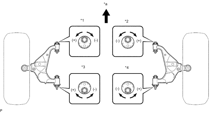
*1 No. 1 Camber Adjusting Cam (LH) *2 No. 1 Camber Adjusting Cam (RH) *3 No. 2 Camber Adjusting Cam (LH) *4 No. 2 Camber Adjusting Cam (RH) *a Front of the Vehicle - - Tech Tips
-
Moving the No. 1 camber adjusting cam to (+) side by one notch changes the caster by approximately +0°07' and the camber by approximately +0°03'.
-
Moving the No. 2 camber adjusting cam to (+) side by one notch changes the caster by approximately +0°06' and the camber by approximately +0°04'.
-
Perform adjustments so that the value is as close as possible to the median of the specified range.
-
-
Tighten the camber adjusting cam nut and camber adjusting cam bolt.
- Torque:
- 185 N*m { 1886 kgf*cm, 136 ft.*lbf }
-
-
INSPECT TOE-IN
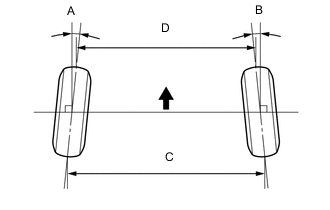

Front of the Vehicle Standard Toe-in (Unloaded Vehicle) Vehicle Model A + B
C - D
GUN156R-STFLHQ Tire Size 265/65R17
for Steel Wheel
A + B: 0°07' +/-5' (0.12° +/-0.08°)
C - D: 1.6 +/-1.0 mm (0.06 +/-0.04 in.)
Tire Size 265/65R17
for Aluminum Wheel
A + B: 0°07' +/-5' (0.12° +/-0.08°)
C - D: 1.7 +/-1.0 mm (0.07 +/-0.04 in.)
GUN156R-STFSHQ A + B: 0°07' +/-5' (0.12° +/-0.08°)
C - D: 1.6 +/-1.0 mm (0.06 +/-0.04 in.)
GUN156R-STFMHQ A + B: 0°07' +/-5' (0.12° +/-0.08°)
C - D: 1.6 +/-1.0 mm (0.06 +/-0.04 in.)
GUN156R-STTLHQ Tire Size 265/65R17
for Steel Wheel
A + B: 0°07' +/-5' (0.12° +/-0.08°)
C - D: 1.6 +/-1.0 mm (0.06 +/-0.04 in.)
Tire Size 265/65R17
for Aluminum Wheel
A + B: 0°07' +/-5' (0.12° +/-0.08°)
C - D: 1.7 +/-1.0 mm (0.07 +/-0.04 in.)
GUN156R-STTSHQ A + B: 0°07' +/-5' (0.12° +/-0.08°)
C - D: 1.7 +/-1.0 mm (0.07 +/-0.04 in.)
GUN156R-STTMHQ A + B: 0°07' +/-5' (0.12° +/-0.08°)
C - D: 1.6 +/-1.0 mm (0.06 +/-0.04 in.)
If the toe-in is not as specified, adjust it at the rack ends.
-
ADJUST TOE-IN
-
Loosen the tie rod end lock nuts.
-
Turn the right and left rack ends by an equal amount to adjust the toe-in to the center value.
-
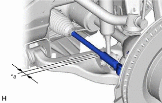
*a Thread Length Adjust the tie rod end sub-assembly so that thread length is within the specified ranges.
Thread Length 17 mm (0.669 in.) or less Tech Tips
Perform adjustments so that the value is as close as possible to the median of the specified range.
-
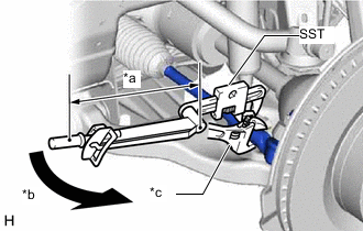
*a Torque Wrench Fulcrum Length *b Turn *c Hold Tighten the tie rod end lock nuts.
- SST
- 09922-10010
- Torque:
- Specified tightening torque
- 60.6 N*m { 618 kgf*cm, 45 ft.*lbf }
Note
Make sure that the boots are not twisted.
Tech Tips
-
Calculate the torque wrench reading when changing the fulcrum length of the torque wrench.
-
When using SST (fulcrum length of 135.5 mm (5.335 in.)) + torque wrench (fulcrum length of 380 mm (14.961 in.)): 44.7 N*m (456 kgf*cm, 33 ft.*lbf)
-
-
INSPECT WHEEL ANGLE
-
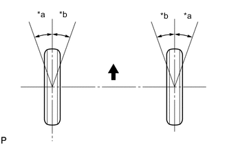
*a Inside *b Outside Front of the Vehicle Turn the steering wheel to the left and right full lock positions, and measure the wheel angle.
Standard Wheel Angle (for Unloaded Vehicle) Inside Wheel Angle Outside Wheel Angle (Reference) 35°00' (33°00' to 36°00')(35.00° (33.00° to 36.00°)) 31°42' (31.70°) If the angles are not as specified, check and adjust the right and left rack end lengths.
-
-
PLACE FRONT WHEELS FACING STRAIGHT AHEAD
-
PERFORM YAW RATE SENSOR ZERO POINT CALIBRATION