REAR DIFFERENTIAL LOCK CONTROL SWITCH INSTALLATION
PROCEDURE
-
INSTALL DIFFERENTIAL LOCK SWITCH
-
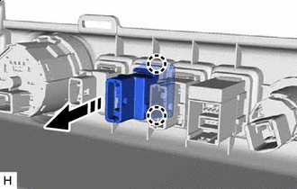

Install in this Direction Attach the 2 claws to install the differential lock switch to the lower instrument cover sub-assembly.
-
Connect the differential lock switch connector.
-
-
INSTALL LOWER INSTRUMENT COVER SUB-ASSEMBLY
-
INSTALL CENTER INSTRUMENT CLUSTER FINISH PANEL SUB-ASSEMBLY
-
INSTALL UPPER CONSOLE PANEL SUB-ASSEMBLY
-
INSTALL SHIFTING HOLE COVER SUB-ASSEMBLY (for Automatic Transmission)
-
INSTALL SHIFT LEVER KNOB SUB-ASSEMBLY
-
INSTALL NO. 1 INSTRUMENT PANEL GARNISH SUB-ASSEMBLY
-
INSTALL NO. 2 INSTRUMENT PANEL GARNISH SUB-ASSEMBLY
-
INSTALL INSTRUMENT PANEL REGISTER BEZEL GARNISH
-
CONNECT CABLE TO NEGATIVE BATTERY TERMINAL
Note
When disconnecting the cable, some systems need to be initialized after the cable is reconnected.
-
CHECK SRS WARNING LIGHT