PARKING BRAKE LEVER INSTALLATION
CAUTION / NOTICE / HINT
Tech Tips
-
Use the same procedure for RHD and LHD vehicles.
-
The procedure listed below is for LHD vehicles.
PROCEDURE
-
INSTALL PARKING BRAKE LEVER SUB-ASSEMBLY
-
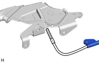
Pass the No. 1 parking brake cable assembly through the parking brake lever sub-assembly.
-
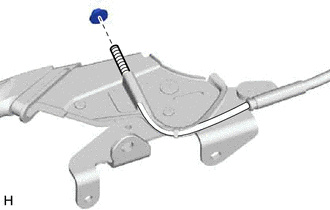
Temporarily install the adjusting nut to the No. 1 parking brake cable assembly.
-
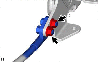
Install the 2 bolts and 2 nuts in the order shown in the illustration.
- Torque:
- 14.5 N*m { 148 kgf*cm, 11 ft.*lbf }
-
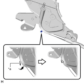
*a Claw 
Return Return the claw to its original position.
Tech Tips
Move the parking brake lever sub-assembly a few times and check for smooth movement.
-
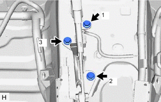
Install the 3 bolts in the order shown in the illustration.
- Torque:
- 12.5 N*m { 127 kgf*cm, 9 ft.*lbf }
-
Install the lock nut.
Tech Tips
Completely tighten the lock nut when adjusting the parking brake lever travel.
-
-
INSTALL PARKING BRAKE SWITCH ASSEMBLY
-
ADJUST PARKING BRAKE LEVER TRAVEL (for TMEE (AAV) Made)
-
ADJUST PARKING BRAKE LEVER TRAVEL (except TMEE (AAV) Made)
-
INSTALL CONSOLE BOX ASSEMBLY