FUEL INJECTION PUMP DISASSEMBLY

PROCEDURE
-
MOUNT INJECTION PUMP ASSEMBLY
-
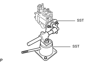
Mount the injection pump assembly on SST.
- SST
- 09241-76022
- 09245-54010
-
-
REMOVE NO. 4 NOZZLE LEAKAGE PIPE
-
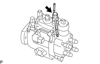
Remove the overflow screw sub-assembly, No. 4 nozzle leakage pipe and 2 air bleeder nipple washers from the injection pump assembly.
-
-
REMOVE FUEL FILTER TO INJECTION PUMP FUEL PIPE
-
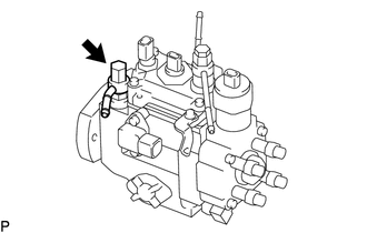
Remove the cap nut, fuel filter to injection pump fuel pipe and 2 air bleeder nipple washers from the injection pump assembly.
-
Remove the screw and air bleeder nipple washer from the injection pump assembly.
-
-
REMOVE WIRING HARNESS BRACKET
-
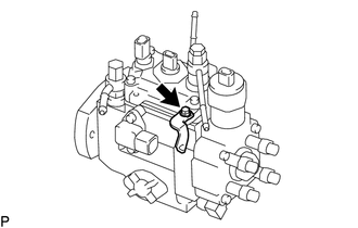
Remove the bolt and wiring harness bracket from the injection pump assembly.
-
-
REMOVE TIMING CONTROL VALVE ASSEMBLY
-
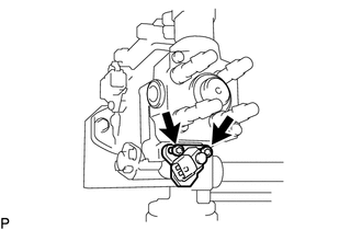
Using a 5 mm hexagon wrench, remove the 2 bolts and timing control valve assembly from the injection pump assembly.
-
-
REMOVE DISTRIBUTIVE HEAD PLUG
-
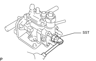
Using SST, remove the distributive head plug from the injection pump assembly.
- SST
- 09260-54012 ( 09262-54010 )
-
Remove the O-ring.
-
-
REMOVE INJECTION PUMP DELIVERY VALVE SUB-ASSEMBLY
-
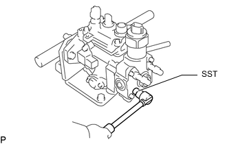
Using SST, remove the 4 injection pump delivery valve holders and 4 delivery valve springs from the injection pump assembly.
- SST
- 09260-54012 ( 09269-54020 )
-
Remove the 4 injection pump delivery valve sub-assemblies and 4 delivery valve gaskets from the injection pump assembly.
Note
Do not touch the sliding surfaces of the injection pump delivery valve sub-assembly with your hand.
Tech Tips
Arrange the injection pump delivery valve sub-assemblies, delivery valve springs and injection pump delivery valve holders in the order they were removed.
-