FUEL SYSTEM ON-VEHICLE INSPECTION
PROCEDURE
-
INSPECT FOR FUEL LEAK
CAUTION:
-
During Active Test mode, the engine speed becomes high and the combustion noise becomes loud, so pay attention.
-
During Active Test mode, the fuel pressure becomes high. Be extremely careful not to expose your eyes, hands, or body to escaping fuel.
Tech Tips
Using the GTS to perform Active Tests allow relays, VSVs, actuators and other items to be operated without removing any parts. This non-intrusive functional inspection can be very useful because intermittent operation may be discovered before parts or wiring is disturbed. Performing Active Tests early in troubleshooting is one way to save diagnostic time. Data List information can be displayed while performing Active Tests.
-
Check that there are no leaks from any part of the fuel system when the engine is stopped. If there is fuel leakage, repair or replace parts as necessary.
-
Start the engine and check that there are no leaks from any part of the fuel system. If there is fuel leakage, repair or replace parts as necessary.
-
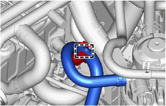
Disconnect the return hose from the common rail assembly.
-
Start the engine and check for fuel leaks from the return pipe.
If there is fuel leakage, replace the common rail assembly.
-
Connect the GTS to the DLC3.
-
Start the engine and turn the GTS on.
-
Enter the following menus: Powertrain / Engine and ECT / Active Test / Test the Fuel Leak.
Powertrain > Engine and ECT > Active TestTester Display Test the Fuel Leak -
If the GTS is not available, fully depress the accelerator pedal quickly. Increase the engine speed to the maximum and maintain that speed for 2 seconds. Repeat this operation several times.
-
Check that there are no leaks from any part of the fuel system.
Note
A return pipe leakage of less than 10 cc (0.6 cu in.) per minute is acceptable.
If there is fuel leakage, repair or replace parts as necessary.
-
Reconnect the return hose to the common rail assembly.
-
-
CHECK PRESSURE DISCHARGE VALVE
Tech Tips
-
This is the procedure for troubleshooting fuel pressure control malfunctions and combustion problems.
-
Malfunctions can be determined by checking the fuel pressure when performing a fuel cut and operating the pressure discharge valve with the GTS.
-
During "Pressure Discharge Valve Check", the GTS measures the fuel pressure while the engine is running, after the engine is stopped, and after the pressure discharge valve operates.
-
Connect the GTS to the DLC3.
-
Turn the ignition switch to ON.
-
Turn the GTS on.
Note
The following conditions must be met:
-
Engine is idling.
-
Vehicle is stopped.
-
Fuel pressure is not extremely high (below 100000 kPa).
-
Fuel pressure is not extremely low (higher than 26000 kPa).
-
Fuel pressure sensor is normal.
-
Battery voltage is higher than 8 V.
Tech Tips
When the common rail pressure is unstable, the fuel pressure may decrease to a level where the test cannot be performed. In this situation, wait until the common rail pressure meets the test condition, and then perform the test.
-
-
Enter the following menus: Powertrain / Engine and ECT / Utility / Pressure Discharge Valve Check.
Powertrain > Engine and ECT > UtilityTester Display Pressure Discharge Valve Check -
Press "Next".
-
Press "Next" again to proceed.
-
Select the check type for "Valve Check for Graph".
-
Press "Next" again to proceed.
-
Press "Start" again to proceed.
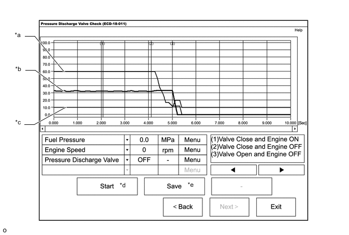
*a Engine Speed *b Fuel Pressure *c Pressure Discharge Valve *d When "Start" is pressed, the pressure discharge valve check begins. *e If "Save" is pressed after the pressure discharge valve check, the data recorded during the valve check can be saved. - -
-
-
Select the check type "Close to Open Check" or "Always Closed Check".
Tech Tips
-
"Close to Open Check" opens the pressure discharge valve after the engine stops.
-
"Always Closed Check" holds the pressure discharge valve closed during the check.
-
Press "Next".
-
-
Perform troubleshooting based on the measurement results.
OK 0.5 MPa or less Tech Tips
-
During "Close to Open Check", if there is no large change in fuel pressure when the pressure discharge valve is closed while the engine is running and after the engine is stopped, and if the value is 0 MPa when the pressure discharge valve is open, the system is normal.
-
Perform "Always Closed Check" if the value is not 0 MPa when the pressure discharge valve is open during "Close to Open Check". If the results are the same as during "Close to Open Check", there is a pressure discharge valve operation malfunction.
-
If a large amount of fuel is leaking, the fuel pressure decreases when the engine is stopped. However, the condition of the pressure discharge valve can still be determined by comparing the measurement results of "Close to Open Check" and "Always Closed Check".
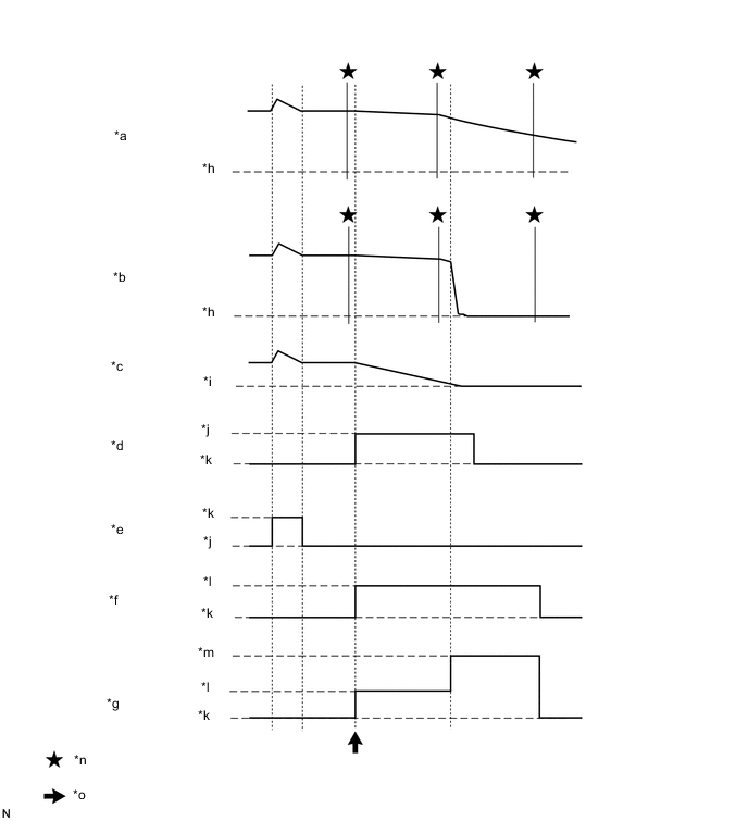
*a Fuel Press
(Always Closed Check)
*b Fuel Press
(Close to Open Check)
*c Engine Speed *d Fuel Cut Operation Signal *e Pressure Discharge Valve Operation
(Prohibition)
*f Pressure Discharge Valve Operation
(Always Closed Check)
*g Pressure Discharge Valve Operation
(Close to Open Check)
*h 0 MPa *i 0 rpm *j On *k Off *l Closed (on) *m Open (on) *n Fuel Press Recorded *o Pressure Discharge Valve Operation Start - - -
-
-
BLEED AIR FROM FUEL SYSTEM
-
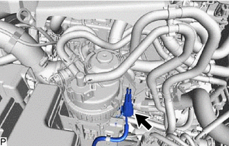
Using the hand pump mounted on the fuel filter cap, bleed the air from the fuel system. Continue pumping until the pump resistance increases.
Note
-
Hand pump pumping speed: Max. 2 strokes/ sec.
-
The hand pump must be pushed with a full stroke during pumping.
-
When the fuel pressure at the supply pump inlet port reaches a saturated pressure, the hand pump resistance increases.
-
If pumping is interrupted during the air bleeding process, fuel in the fuel line may return to the fuel tank assembly. Continue pumping until the hand pump resistance increases.
-
If the hand pump resistance does not increase despite consecutively pumping 200 times or more, there may be a fuel leak between the fuel tank assembly and fuel filter assembly, the hand pump may be malfunctioning, or the vehicle may have run out of fuel.
-
If air bleeding using the hand pump is incomplete, the common rail assembly pressure does not rise to the pressure range necessary for normal use, and the engine cannot be started.
-
-
Check if the engine starts.
Note
-
Even if air bleeding using the hand pump has been completed, the starter assembly may need to be cranked for 10 seconds or more to start the engine.
-
Do not crank the engine continuously for more than 20 seconds. The battery may be discharged.
-
Use a fully-charged battery.
-
When the engine can be started, proceed to the next step.
-
If the engine cannot be started, bleed the air again using the hand pump until the hand pump resistance increases (refer to the procedures above). Then start the engine.
-
-
Turn the ignition switch off.
-
Connect the GTS to the DLC3.
-
Turn the ignition switch to ON and turn the GTS on.
-
Clear the DTCs.
-
Start the engine.*1
-
Enter the following menus: Powertrain / Engine and ECT / Active Test / Test the Fuel Leak.*2
Powertrain > Engine and ECT > Trouble Codes -
Perform the following test 5th times with on/off intervals of 10 seconds: Active Test / Test the Fuel Leak.*3
-
Allow the engine to idle for 3 minutes or more after performing the Active Test for the 5th time.
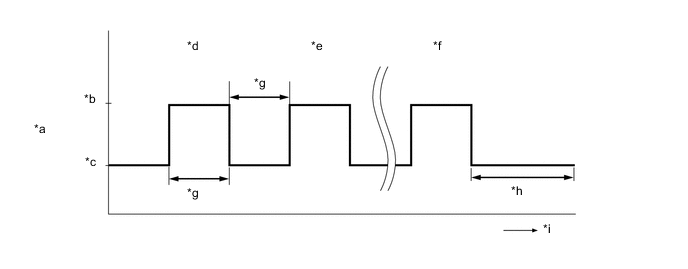
*a Active Test Operation *b ON *c OFF *d 1st time *e 2nd time *f 5th time *g 10 seconds *h 3 minutes *i Time - - Tech Tips
When the Active Test "Test the Fuel Leak" is used to change the pump control mode, the actual fuel pressure inside the common rail assembly drops below the target fuel pressure when the Active Test is off, but this is normal and does not indicate a pump malfunction.
-
Enter the following menus: Powertrain / Engine and ECT / Trouble Codes.
Powertrain > Engine and ECT > Trouble Codes -
Read Current DTCs.
-
Clear the DTCs.
Tech Tips
It is necessary to clear the DTCs as DTC P1604 or P1605 may be stored when air is bled from the fuel system after replacing or repairing fuel system parts.
-
Repeat steps *1 to *3.
-
Enter the following menus: Powertrain / Engine and ECT / Trouble Codes.
Powertrain > Engine and ECT > Trouble Codes -
Read Current DTCs.
OK No DTCs are output.
-
-
CHECK FUEL SYSTEM WARNING LIGHT AND DRAIN WATER
-
w/ Multi-information Display:
Check the fuel system warning is displayed on the multi-information display, replace the fuel filter element assembly Click here or drain the water in the fuel filter assembly.
-
w/o Multi-information Display:
Check the fuel system warning light in the combination meter assembly and either replace the fuel filter element assembly Click here or drain the water in the fuel filter assembly based on the instructions shown in the illustration.
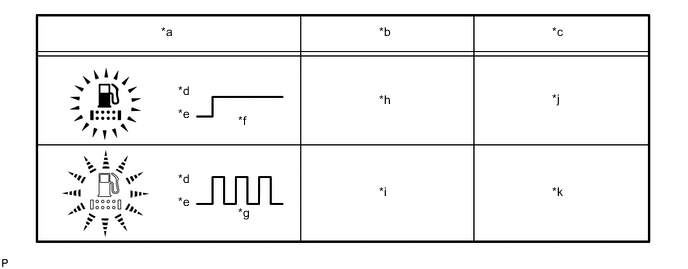
*a Fuel System Warning Light *b Fuel Filter Condition *c Necessary Procedure *d On *e Off *f Illuminate *g Blinking *h Clogged *i Water Level Warning *j Replace the Fuel Filter Element Assembly *k Drain the Water - - -
Drain water.
-
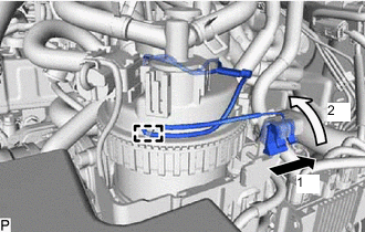
Detach the clamp and disconnect the No. 1 fuel hose from the No. 2 fuel pipe clamp.
-
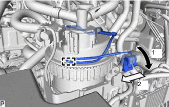
Disconnect the clamp and slide the lead wire as shown in the illustration to remove it.
-
Disconnect the level warning switch connector.
-
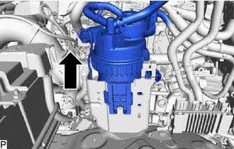
Slide the fuel filter assembly and lift it up.
-
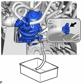
Connect a hose to the drain cock. Place the other end of the hose into a container under the drain cock.
-
Loosen the drain cock to drain water.
-
Operate the hand pump until fuel begins to run out.
-
Tighten the drain cock by hand.
Note
Do not use any tools in this procedure.
-

Slide the fuel filter assembly to install it.
-
Connect the level warning switch connector.
-
Attach the clamp and slide the lead wire as shown in the illustration to install it.
-
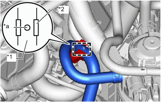
*1 No. 1 Fuel Hose *2 No. 2 Fuel Pipe Clamp *a Paint Mark Attach the clamp and connect the No. 1 fuel hose to the No. 2 fuel pipe clamp.
Tech Tips
Make sure that the paint mark of the No. 1 fuel hose is positioned as shown in the illustration.
-
-