FUEL INJECTOR REMOVAL

CAUTION / NOTICE / HINT
The necessary procedures (adjustment, calibration, initialization, or registration) that must be performed after parts are removed, installed, or replaced during the injector assembly removal/installation are shown below.
| Replacement Part or Procedure | Necessary Procedures | Effects/Inoperative when not Performed | Link |
|---|---|---|---|
| Injector assembly |
|
Engine starting |
CAUTION:
To prevent burns, do not touch the engine, exhaust manifold or other high temperature components while the engine is hot.
Note
-
When replacing the parts in the following chart (A), replace the No. 1 injection pipe sub-assembly, No. 2 injection pipe sub-assembly, No. 3 injection pipe sub-assembly, No. 4 injection pipe sub-assembly and/or fuel inlet pipe sub-assembly with new ones.
-
After removing the No. 1 injection pipe sub-assembly, No. 2 injection pipe sub-assembly, No. 3 injection pipe sub-assembly, No. 4 injection pipe sub-assembly and fuel inlet pipe sub-assembly, clean them with a brush and compressed air.
Replaced Parts (A) Pipes Requiring New Replacement
-
Injector assembly (including shuffling the injector assemblies between the cylinders)
-
Common rail assembly
-
Cylinder head sub-assembly
-
No. 1 injection pipe sub-assembly
-
No. 2 injection pipe sub-assembly
-
No. 3 injection pipe sub-assembly
-
No. 4 injection pipe sub-assembly
-
Supply pump assembly
-
Common rail assembly
-
Cylinder block sub-assembly
-
Cylinder head sub-assembly
-
Cylinder head gasket
-
Timing Gear Case Assembly
Fuel inlet pipe sub-assembly -
PROCEDURE
-
PRECAUTION
Note
After turning the ignition switch off, waiting time may be required before disconnecting the cable from the battery terminal. Therefore, make sure to read the disconnecting the cable from the battery terminal notice before proceeding with work.
-
DISCONNECT CABLE FROM NEGATIVE BATTERY TERMINAL
Note
When disconnecting the cable, some systems need to be initialized after the cable is reconnected.
-
REMOVE INTERCOOLER ASSEMBLY
-
CHECK INJECTOR COMPENSATION CODE
Tech Tips
If the injector compensation code is not correctly registered, it may cause malfunctions.
-
Read the injector compensation code.
-
Check that the compensation code of the installed injector assembly is the same as the code registered in the ECM. If the code is not the same, register the injector compensation code on the injector assembly.
-
-
REMOVE NO. 1, NO. 2 AND NO. 3 INJECTION PIPE SUB-ASSEMBLY
Note
-
After removing the No. 1 injection pipe sub-assembly, No. 2 injection pipe sub-assembly and No. 3 injection pipe sub-assembly, cover the outlets on the common rail assembly with tape to keep out foreign matter.
-
After removing the No. 1 injection pipe sub-assembly, No. 2 injection pipe sub-assembly and No. 3 injection pipe sub-assembly, put it in a plastic bag to prevent foreign matter from contaminating its injector assembly inlet.
-
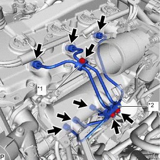
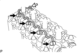
*1 No. 2 Injection Pipe Clamp *2 No. 3 Injection Pipe Clamp Remove the bolt and No. 2 injection pipe clamp from the No. 1 injection pipe sub-assembly and No. 2 injection pipe sub-assembly.
-
Remove the 2 nuts and No. 3 injection pipe clamp from the No. 1 injection pipe sub-assembly, No. 2 injection pipe sub-assembly and No. 3 injection pipe sub-assembly.
-
Using a 17 mm union nut wrench, loosen the union nuts and remove the No. 1 injection pipe sub-assembly, No. 2 injection pipe sub-assembly and No. 3 injection pipe sub-assembly from the injector assembly and common rail assembly.
-
-
REMOVE NO. 4 INJECTION PIPE SUB-ASSEMBLY
Note
If an injection pipe clamp is removed from the No. 4 injection pipe sub-assembly, replace the injection pipe clamp with a new one.
-
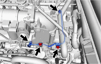
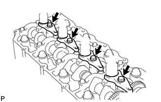
Remove the 2 bolts and disconnect the 2 injection pipe clamps from the intake manifold.
-
Using a 17 mm union nut wrench, loosen the union nuts and remove the No. 4 injection pipe sub-assembly from the injector assembly and common rail assembly.
-
-
REMOVE NO. 2 NOZZLE LEAKAGE PIPE ASSEMBLY
-
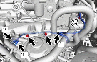
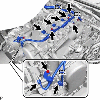
*1 Fuel Hose *2 No. 1 Fuel Hose *3 No. 2 Fuel Hose 
Union Bolt Slide the 3 clamps and disconnect the fuel hose, No. 1 fuel hose and No. 2 fuel hose from the No. 2 nozzle leakage pipe assembly.
-
Remove the union bolt, 2 bolts, No. 2 nozzle leakage pipe assembly and gasket from the intake manifold and cylinder head sub-assembly.
-
-
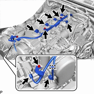
DISCONNECT ENGINE WIRE
-
for LHD:
-
Disconnect the connector from the diesel throttle body assembly.
-
Disconnect the 4 connectors from the 4 injector assemblies.
-
Disconnect the connector from the engine coolant temperature sensor.
-
Disconnect the connector from the compressor assembly.
-
Remove the 3 bolts.
-
Detach the 3 clamps and disconnect the engine wire from the cylinder head cover sub-assembly.
-
-
for RHD:
-
Disconnect the connector from the diesel throttle body assembly.
-
Disconnect the 4 connectors from the 4 injector assemblies.
-
Disconnect the connector from the engine coolant temperature sensor.
-
Disconnect the connector from the compressor assembly.
-
Remove the 3 bolts.
-
Detach the clamp and disconnect the engine wire from the cylinder head cover sub-assembly.
-
-
-
REMOVE CYLINDER HEAD COVER SUB-ASSEMBLY
Note
If the cylinder head cover sub-assembly is removed, replace the 4 No. 3 cylinder head cover gaskets with new ones.
-
Disconnect the PCV hose from the cylinder head cover sub-assembly.
-
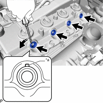
*a Cutout Part Using a small screwdriver, remove the 4 nozzle holder seals by prying between the nozzle holder seal and the cutout part of the cylinder head cover sub-assembly.
-
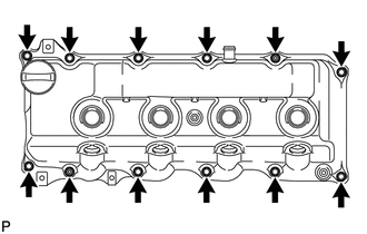
Remove the 10 bolts, 2 nuts, cylinder head cover sub-assembly and cylinder head cover gasket from the cylinder head sub-assembly.
-
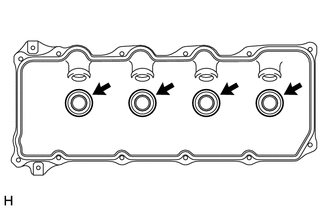
Remove the 4 No. 3 cylinder head cover gaskets from the cylinder head cover sub-assembly.
-
-
REMOVE INJECTOR ASSEMBLY
-
Union Bolt Remove the union bolt, 4 injector hollow screws, 5 gaskets and nozzle leakage pipe assembly from the injector assembly and cylinder head sub-assembly.
Note
-
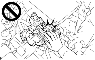
When removing the nozzle leakage pipe assembly, place a cushion under the nozzle leakage pipe assembly.
-
Be careful not to deform or scratch the union seal surface.
-
After removing the nozzle leakage pipe assembly, put it in a plastic bag to prevent foreign matter from contaminating its injector assembly inlet.
-
-
Remove the 4 bolts, 4 washers, 4 No. 1 nozzle holder clamps and 4 injector assemblies from the cylinder head sub-assembly.
Tech Tips
Arrange the injector assemblies, No. 1 nozzle holder clamps, washers and bolts in the correct order.
-
Remove the O-ring from each injector assembly.
-
Remove the 4 injection nozzle seats from the cylinder head sub-assembly.
-