CYLINDER BLOCK REASSEMBLY

PROCEDURE
-
INSTALL STUD BOLT
Note
If a stud bolt is deformed or its threads are damaged, replace it.
-
Install the stud bolts as shown in the illustration.
- Torque:
- 14.5 N*m { 148 kgf*cm, 11 ft.*lbf }
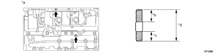
*a RH Side *b 16 mm (0.630 in.) *c 10 mm (0.394 in.) *d 35 mm (1.38 in.)
-
-
INSTALL CYLINDER BLOCK WATER DRAIN COCK SUB-ASSEMBLY
-
Apply adhesive to 2 or 3 threads of the cylinder block water drain cock sub-assembly.
Adhesive Toyota Genuine Adhesive 1324, Three Bond 1324 or equivalent -
*a Port *b Downward Install the cylinder block water drain cock sub-assembly.
- Torque:
- 57 N*m { 581 kgf*cm, 42 ft.*lbf }
Tech Tips
-
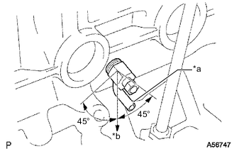
After tightening the drain cock to the specified torque, rotate the drain union clockwise until its drain port is facing downward.
-
The drain port may be set within 45° of either side of the prescribed position.
Note
-
Install the cylinder block water drain cock sub-assembly within 3 minutes after applying adhesive.
-
Do not expose the cylinder block water drain cock sub-assembly to coolant within 1 hour of installation.
-
Rotate the cylinder block water drain cock sub-assembly clockwise to the position shown in the illustration.
Note
-
Do not rotate the cylinder block water drain cock sub-assembly by more than 1 revolution (360°) after tightening the cylinder block water drain cock sub-assembly to the specified torque.
-
Do not loosen the cylinder block water drain cock sub-assembly after setting it correctly.
-
-
-
INSTALL NO. 1 OIL NOZZLE SUB-ASSEMBLY
-
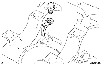
Align the pin of the No. 1 oil nozzle sub-assembly with the pin hole of the cylinder block sub-assembly.
-
Install the 4 No. 1 oil nozzle sub-assemblies with the 4 check valves.
- Torque:
- 25.5 N*m { 260 kgf*cm, 19 ft.*lbf }
-
-
INSTALL PISTON WITH PIN SUB-ASSEMBLY
-
Using snap ring pliers, install a new snap ring on one side of the piston pin hole.
-
Gradually heat the piston to approximately 60°C (140°F).
-
Coat the piston pin with engine oil.
-
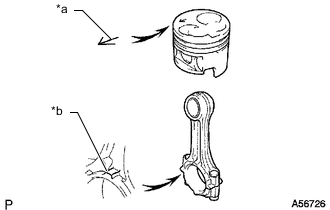
*a Front Mark (Arrow) *b Front Mark (Protrusion) Align the front marks of the piston and connecting rod sub-assembly, connect the connecting rod sub-assembly to the piston, and then push in the piston pin with your thumb.
-
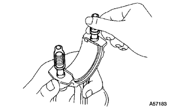
Check the fit between the piston and piston pin. Try to move the piston back and forth on the piston pin.
-
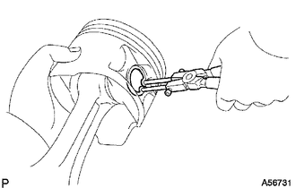
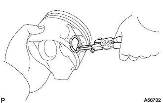
Using a small screwdriver, install a new snap ring on the other side of the piston pin hole.
-
-
INSTALL PISTON RING SET
-
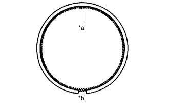
*a Coil Joint *b Oil Ring End Gap Install the coil and oil ring by hand. Install the piston rings.
Tech Tips
Make sure the end gap of the oil ring and the coil joint are on opposite sides.
-
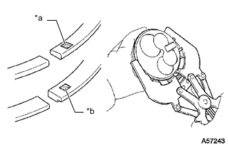
*a No. 1 Piston Ring Code Mark *b No. 2 Piston Ring Code Mark Using a piston ring expander, install the No. 1 piston ring and No. 2 piston ring with the code marks facing upward.
Code Mark Item Specified Condition No. 1 piston ring 1N No. 2 piston ring 2N -
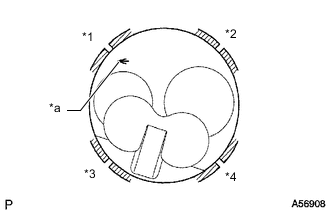
*1 No. 1 Piston Ring *2 Oil Ring *3 Coil *4 No. 2 Piston Ring *a Front Mark (Arrow) Position the piston rings so that the ring ends are as shown in the illustration.
Note
Do not align the ring ends.
-
-
INSTALL CRANKSHAFT BEARING
Tech Tips
Upper crankshaft bearings have an oil groove and oil hole. Lower crankshaft bearings do not.
-
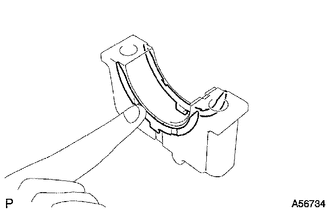
Align the crankshaft bearing claw with the claw groove of the cylinder block sub-assembly and push in the 5 upper crankshaft bearings.
-
Align the crankshaft bearing claw with the claw groove of the crankshaft bearing cap and push in the 5 lower crankshaft bearings.
-
-
INSTALL CRANKSHAFT
-
Place the crankshaft on the cylinder block sub-assembly.
-
Push the crankshaft in one direction and install one crankshaft thrust washer to the No. 3 journal position with the oil groove facing outward.
-
Push the crankshaft in the opposite direction and install the other crankshaft thrust washer to the No. 3 journal position with the oil groove facing outward.
-
Install the 2 crankshaft thrust washers to the No. 3 bearing cap with the grooves facing outward.
-
Place the crankshaft on the cylinder block sub-assembly.
-
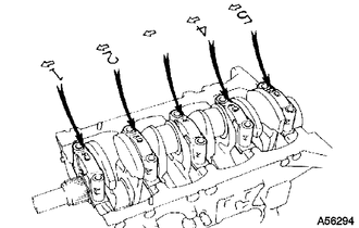
Install the 5 crankshaft bearing caps in their proper locations.
-
Install the crankshaft bearing cap set bolts.
Tech Tips
-
The crankshaft bearing cap set bolts are tightened in 2 progressive steps.
-
If a crankshaft bearing cap set bolt is broken or deformed, replace it.
-
Apply a light coat of engine oil to the threads and under the bolt heads of the crankshaft bearing cap set bolts.
-
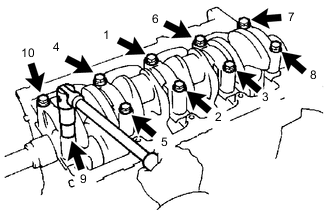
Install and uniformly tighten the 10 crankshaft bearing cap set bolts of the crankshaft bearing caps in several passes in the sequence shown in the illustration.
- Torque:
- 105 N*m { 1071 kgf*cm, 77 ft.*lbf }
-
-
Check that the crankshaft turns smoothly.
-
-
REPLACE CRANKSHAFT THRUST CLEARANCE
-
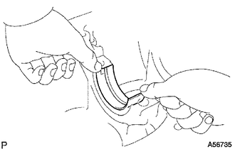
INSTALL CONNECTING ROD BEARING
-
Align the connecting rod bearing claw with the groove of the connecting rod sub-assembly or connecting rod cap.
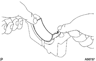
-
Install the connecting rod bearings to the connecting rod sub-assembly and connecting rod cap.
-
-
INSTALL PISTON AND CONNECTING ROD
-
Apply engine oil to the cylinder walls, the pistons and the surfaces of the connecting rod bearings.
-
Check the positions of the piston ring ends.
-
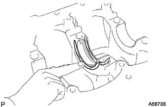
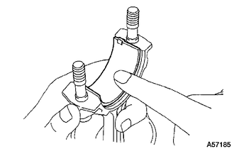
Cover the connecting rod bolts with a short piece of hose to protect the crankshaft and cylinder bore from damage.
-
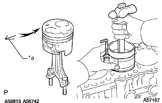
*a Front Mark Using a piston ring compressor, push the correctly numbered piston and connecting rod assembly into the cylinder with the front mark of the piston facing forward.
-
Place the connecting rod cap on the connecting rod sub-assembly.
-
Match each numbered connecting rod cap with the correct connecting rod sub-assembly.
-
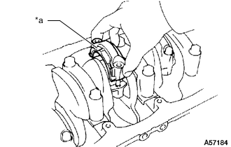
*a Front Mark Install the connection rod cap with the front mark facing forward.
-
-
Install the connecting rod cap nuts.
Tech Tips
-
The connecting rod nuts are tightened in 2 progressive steps.
-
If any connecting rod bolt is broken or deformed, replace it.
-
Apply a light coat of engine oil to the threads and under the heads of the connecting rod cap nuts.
-
Install and alternately tighten the nuts of the connecting rod cap in several passes.
- Torque:
- 54 N*m { 551 kgf*cm, 40 ft.*lbf }
Tech Tips
If any one of the connecting rod cap nuts does not meet the torque specification, replace the connecting rod cap nut.
-
-
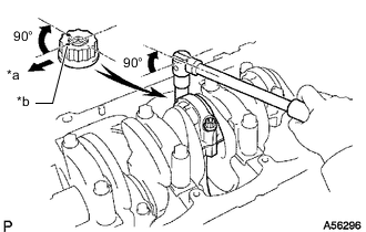
*a Front *b Paint Mark Mark the front of each connecting rod cap nut with paint.
-
Tighten the connecting rod cap nuts by 90° as shown in the illustration.
-
Check that the painted marks are now at a 90° angle to the front.
-
Check that the crankshaft turns smoothly.
-
-
INSPECT CONNECTING ROD THRUST CLEARANCE
-
INSTALL CYLINDER BLOCK OIL ORIFICE
-
Using a 6 mm hexagon socket wrench, install the cylinder block oil orifice.
- Torque:
- 11 N*m { 112 kgf*cm, 8 ft.*lbf }
-