ENGINE UNIT INSPECTION

PROCEDURE
-
INSPECT INTAKE MANIFOLD
-
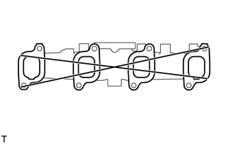
Using a precision straightedge and feeler gauge, measure the warpage of the surface of the intake manifold that contacts the cylinder head sub-assembly.
Maximum warpage 0.4 mm (0.0157 in.) If the warpage is more than the maximum, replace the intake manifold.
-
-
INSPECT EXHAUST MANIFOLD
-
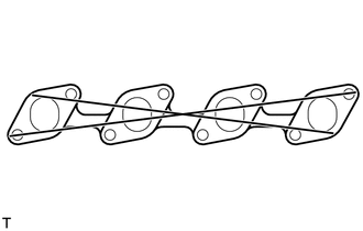
Using a precision straightedge and feeler gauge, measure the warpage of the surface of the exhaust manifold that contacts the cylinder head sub-assembly.
Maximum warpage 0.4 mm (0.0157 in.) If the warpage is more than the maximum, replace the exhaust manifold.
-
-
INSPECT CAMSHAFT
-
Inspect the circle runout.
-
Place the camshaft on V-blocks.
-
Using a dial indicator, measure the circle runout at the center journal.
Maximum circle runout 0.1 mm (0.00394 in.) If the circle runout is more than the maximum, replace the camshaft.
-
-
Using a micrometer, measure the cam lobe height.
Standard Cam Lobe Height Cam Lobe Specified Condition Intake 54.89 to 54.91 mm (2.1610 to 2.1618 in.) Exhaust 54.99 to 55.01 mm (2.1650 to 2.1657 in.) Minimum Cam Lobe Height Cam Lobe Specified Condition Intake 54.39 mm (2.141 in.) Exhaust 54.49 mm (2.145 in.) If the cam lobe height is less than the minimum, replace the camshaft.
-
-
INSPECT CAMSHAFT OIL CLEARANCE
-
Clean the camshaft bearing caps and journals.
-
Check the camshaft bearings for flaking and scoring.
If the bearings are damaged, replace the camshaft bearing caps and cylinder head sub-assembly as a set.
-
Install the bearings to the camshaft bearing caps and cylinder head sub-assembly.
-
Place the camshaft on the cylinder head sub-assembly.
-
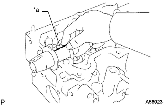
*a Plastigage Lay a strip of Plastigage across each of the journals.
-
Install the camshaft bearing caps.
Note
Do not turn the camshaft.
-
Remove the camshaft bearing caps.
-
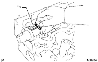
*a Plastigage Measure the Plastigage at its widest point.
Standard oil clearance 0.022 to 0.074 mm (0.000866 to 0.00291 in.) Maximum oil clearance 0.1 mm (0.00394 in.) If the oil clearance is more than the maximum, replace the camshaft bearings. If necessary, replace the camshaft and cylinder head sub-assembly.
-
Completely remove the Plastigage.
-
Remove the camshaft.
-
-
INSPECT CAMSHAFT THRUST CLEARANCE
-
Install the camshaft.
-
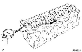
Using a dial indicator, measure the thrust clearance while moving the camshaft back and forth.
Standard thrust clearance 0.08 to 0.28 mm (0.00315 to 0.0110 in.) Maximum thrust clearance 0.35 mm (0.0138 in.) If the thrust clearance is more than the maximum, replace the camshaft bearings. If necessary, replace the camshaft and cylinder head sub-assembly.
-
Remove the camshaft.
-
-
INSPECT CYLINDER HEAD SET BOLT
-
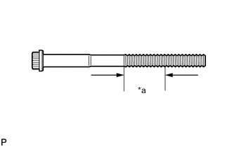
*a Measurement Area Using a vernier caliper, measure the diameter of the most elongated threads in the measurement area.
Standard outside diameter 11.76 to 11.97 mm (0.463 to 0.471 in.) Minimum outside diameter 11.6 mm (0.457 in.) Tech Tips
If a visual check reveals no excessively thin areas, check the center of the cylinder head set bolt (see illustration) and find the area that has the smallest diameter.
If the diameter is less than the minimum, replace the cylinder head set bolt.
-