VALVE CLEARANCE ADJUSTMENT

CAUTION / NOTICE / HINT
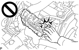
CAUTION:
To prevent burns, do not touch the engine, exhaust manifold or other high temperature components while the engine is hot.
PROCEDURE
-
REMOVE AIR CLEANER CAP AND HOSE
-
REMOVE INTAKE PIPE
-
REMOVE CYLINDER HEAD COVER SUB-ASSEMBLY
-
SET NO. 1 CYLINDER TO TDC/COMPRESSION
-
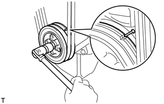
Turn the crankshaft pulley and align its groove with the timing pointer.
-
Check that the valve lifters for the No. 1 cylinder are loose and the valve lifters for the No. 4 cylinder are tight.
If not, turn the crankshaft 1 revolution (360°) and align the mark as above.
-
-
INSPECT VALVE CLEARANCE
-
Check only the valves indicated.
-
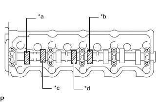
*a No. 1 Exhaust *b No. 3 Exhaust *c No. 1 Intake *d No. 2 Intake Using a feeler gauge, measure the clearance between the valve lifter and camshaft sub-assembly.
Standard Valve Clearance (Cold) Item Specified Condition Intake 0.2 to 0.3 mm (0.00787 to 0.0118 in.) Exhaust 0.4 to 0.5 mm (0.0158 to 0.0197 in.) -
Record the out-of-specification valve clearance measurements. They will be used later to determine the required replacement adjusting valve adjusting shim.
-
-
Turn the crankshaft 360° and align the mark as above.
-
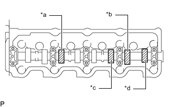
*a No. 2 Exhaust *b No. 4 Exhaust *c No. 3 Intake *d No. 4 Intake Check only the valves indicated.
-
Using a feeler gauge, measure the clearance between the valve lifter and camshaft sub-assembly.
Standard Valve Clearance (Cold) Item Specified Condition Intake 0.2 to 0.3 mm (0.00787 to 0.0118 in.) Exhaust 0.4 to 0.5 mm (0.0158 to 0.0197 in.) -
Record the out-of-specification valve clearance measurements. They will be used later to determine the required replacement valve adjusting shim.
-
-
-
ADJUST VALVE CLEARANCE
-
Remove the valve adjusting shim.
-
Turn the crankshaft so that the cam lobe of the camshaft on the valve being adjusted points upward.
-
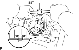
Using SST, press down the valve lifter.
- SST
- 09248-64011
-
Position the notch of the valve lifter so that it faces the exhaust manifold side.
-
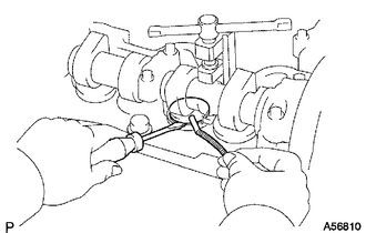
Remove the valve adjusting shim with a screwdriver and magnet hand.
-
-
Determine the replacement valve adjusting shim size according to the formula and charts below.
-
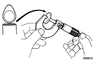
Using a micrometer, measure the thickness of the removed valve adjusting shim.
-
Calculate the thickness of a new valve adjusting shim so that the valve clearance comes within the specified range.
T = Thickness of removed valve adjusting shim
A = Measured valve clearance
N = Thickness of new valve adjusting shim
Intake N = T + (A - 0.25 mm (0.00984 in.)) Exhaust N = T + (A - 0.45 mm (0.0177 in.)) -
Select a new valve adjusting shim with a thickness as close as possible to the calculated value.
Tech Tips
Valve adjusting shims are available in 17 sizes in increments of 0.05 mm (0.00197 in.), from 2.50 mm (0.0984 in.) to 3.30 mm (0.130 in.).
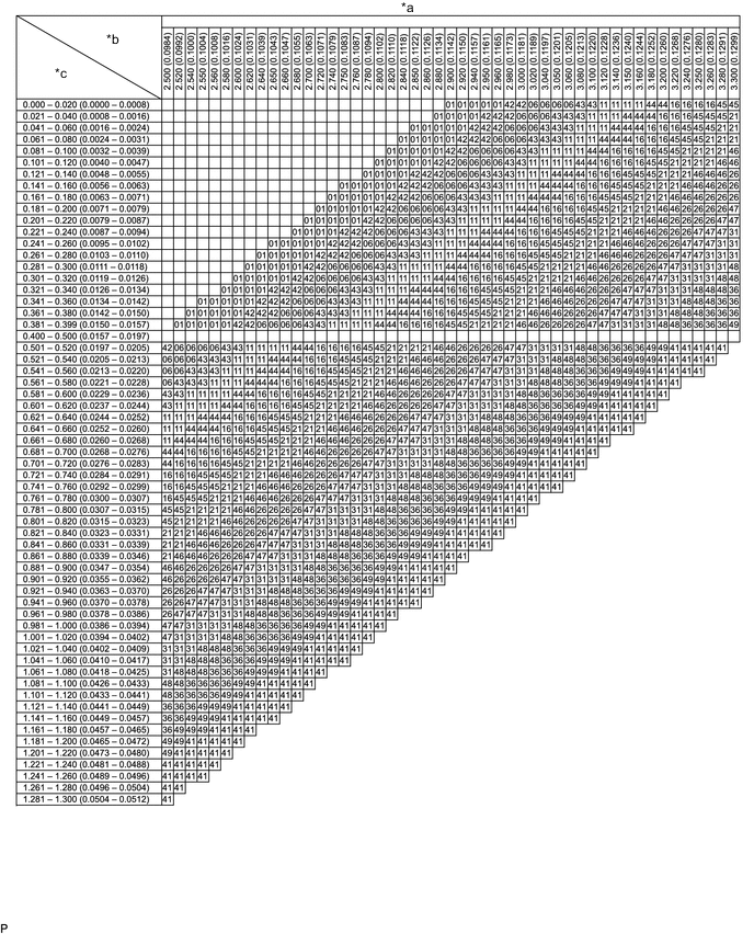
*a Valve Adjusting Shim Selection Chart (Intake) *b Removed Valve Adjusting Shim Thickness mm (in.) *c Measure Clearance mm (in.) - - Intake valve clearance (Cold) 0.2 to 0.3 mm (0.00788 to 0.0118 in.) EXAMPLE A 2.8 mm (0.110 in.) shim is installed and the measured clearance is 0.350 mm (0.0138 in.). Replace the 2.8 mm (0.110 in.) shim with a No. 21 shim. New Valve Adjusting Shim Thickness mm (in.) Shim No. Thickness Shim No. Thickness 01 2.50 (0.0984) 46 2.95 (0.116) 42 2.55 (0.100) 26 3.00 (0.118) 06 2.60 (0.102) 47 3.05 (0.120) 43 2.65 (0.104) 31 3.10 (0.122) 11 2.70 (0.106) 48 3.15 (0.124) 44 2.75 (0.108) 36 3.20 (0.126) 16 2.80 (0.110) 49 3.25 (0.128) 45 2.85 (0.112) 41 3.30 (0.130) 21 2.90 (0.114) - - 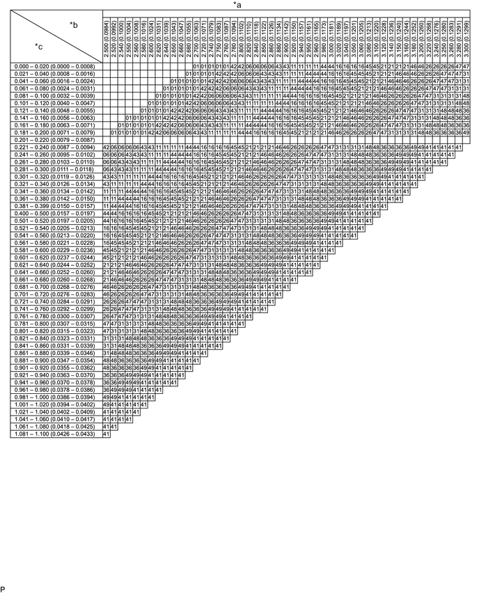
*a Valve Adjusting Shim Selection Chart (Exhaust) *b Removed Valve Adjusting Shim Thickness mm (in.) *c Measure Clearance mm (in.) - - Exhaust valve clearance (Cold) 0.4 to 0.5 mm (0.0158 to 0.0196 in.) EXAMPLE A 2.80 mm (0.110 in.) shim is installed and the measured clearance is 0.350 mm (0.0138 in.). Replace the 2.80 mm (0.110 in.) shim with a No. 11 shim. New Valve Adjusting Shim Thickness mm (in.) Shim No. Thickness Shim No. Thickness 01 2.50 (0.0984) 46 2.95 (0.116) 42 2.55 (0.100) 26 3.00 (0.118) 06 2.60 (0.102) 47 3.05 (0.120) 43 2.65 (0.104) 31 3.10 (0.122) 11 2.70 (0.106) 48 3.15 (0.124) 44 2.75 (0.108) 36 3.20 (0.126) 16 2.80 (0.110) 49 3.25 (0.128) 16 2.85 (0.112) 41 3.30 (0.130) 21 2.90 (0.114) - -
-
-
Install a new valve adjusting shim.
-
Remove SST.
-
Recheck valve clearance.
-
-
INSTALL CYLINDER HEAD COVER SUB-ASSEMBLY
-
INSTALL INTAKE PIPE
-
INSTALL AIR CLEANER CAP AND HOSE
-
INSPECT ENGINE IDLE SPEED
-
INSPECT MAXIMUM ENGINE SPEED