ENGINE ON-VEHICLE INSPECTION

CAUTION / NOTICE / HINT
CAUTION:
To prevent injury due to contact with an operating fan and generator V belt or cooling fan, keep your hands and clothing away from the fan and generator V belt and cooling fans when working in the engine compartment with the engine running.
PROCEDURE
-
INSPECT ENGINE COOLANT
-
INSPECT ENGINE OIL
-
INSPECT BATTERY
-
INSPECT AIR CLEANER FILTER ELEMENT SUB-ASSEMBLY
-
Remove the air cleaner filter element sub-assembly from the air cleaner case sub-assembly.
-
Check that the air cleaner filter element sub-assembly is not excessively dirty.
If the air cleaner filter element sub-assembly is excessively dirty, replace the air cleaner filter element sub-assembly.
If cleaning the air cleaner filter element sub-assembly, blow compressed air to clean it.
Note
-
Do not start the engine with the air cleaner filter element sub-assembly removed, as this may damage the engine.
-
When using an air cleaner filter element sub-assembly that uses compressed air, wear safety glasses and a dust mask in order to protect your health.
Tech Tips
When an excessive amount of dirt is present, replace the air cleaner filter element sub-assembly.
-
-
Reinstall the air cleaner filter element sub-assembly to the air cleaner case sub-assembly.
-
-
INSPECT INJECTION TIMING
-
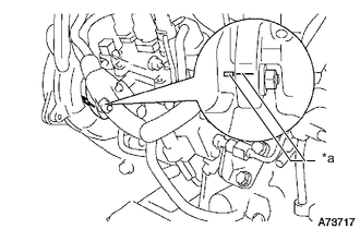
*a Matchmark Using a mirror, check that the matchmarks of the injection pump flange and timing belt case sub-assembly are aligned.
-
-
ADJUST INJECTION TIMING
-
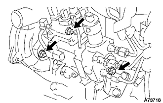
Loosen the following nuts and bolts.
-
The bolt holding the injection pump assembly to the No. 1 injection pump stay.
-
The 2 nuts holding the injection pump assembly to the timing belt case sub-assembly.
-
-
Align the matchmark by slightly tilting the injection pump assembly.
-
Tighten the following nuts and bolts.
-
The 2 nuts holding the injection pump assembly to the timing belt case sub-assembly.
- Torque:
- 20.5 N*m { 209 kgf*cm, 15 ft.*lbf }
-
The bolt holding the injection pump assembly to the No. 1 injection pump stay.
- Torque:
- 26 N*m { 265 kgf*cm, 19 ft.*lbf }
-
-
-
INSPECT ENGINE IDLE SPEED
-
Warm up and stop the engine.
-
When using the GTS:
Tech Tips
-
For more information about the GTS, refer to its operator's manual.
-
If the GTS is not available, use a tachometer as a substitute.
-
Connect the GTS to the DLC3.
-
Start the engine and idle it.
-
Enter the following menus: Powertrain / Engine and ECT / Data List / Engine Speed.
Powertrain > Engine > Data ListTester Display Engine Speed
-
-
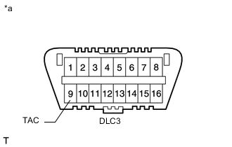
*a Front view of DLC3 When not using the GTS:
-
Connect a tester probe of a tachometer to terminal 9 (TAC) of the DLC3 with SST.
- SST
- 09843-18040
-
Start the engine and idle it.
-
-
Inspect the engine idle speed.
Standard idle speed 650 to 750 rpm Note
-
Turn all the electrical systems and A/C off.
-
When checking the idle speed, move the shift lever to neutral.
-
-
Turn the ignition switch off.
-
Disconnect the GTS or tachometer tester probe from the DLC3.
-
-
INSPECT MAXIMUM ENGINE SPEED
-
Start the engine.
-
Fully depress the accelerator pedal.
-
Check the maximum engine speed.
Maximum engine speed 4850 to 4950 rpm
-
-
INSPECT COMPRESSION
Tech Tips
If there is a lack of power, excessive oil consumption or poor fuel economy is suspected. Measure the compression pressure.
-
Warm up and stop the engine.
-
Remove the glow plugs.
-
Disconnect the spill control valve connector.
-
Inspect the cylinder compression pressure.
-
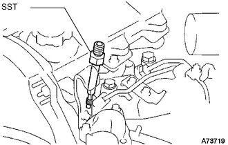
Install SST (attachment) to the glow plug hole.
- SST
- 09992-19015 ( 09992-10070 )
- Torque:
- 13 N*m { 133 kgf*cm, 10 ft.*lbf }
-
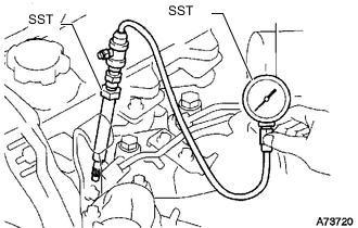
Connect SST (gauge assembly) to SST (attachment D).
- SST
- 09992-19015 ( 09992-10010 )
-
Fully open the throttle valve, and start the engine.
-
While cranking the engine, measure the compression pressure.
Standard compression pressure 3138 kPa (32.0 kgf/cm2, 455 psi) or higher Minimum pressure 1961 kPa (20.0 kgf/cm2, 284 psi) Difference between each cylinder 490 kPa (5.0 kgf/cm2, 71 psi) or less Note
-
Use a fully-charged battery so the engine speed can be increased to 250 rpm or more.
-
Inspect the other cylinders in the same way.
-
Measure the compression as quickly as possible.
-
-
If the cylinder compression is low, pour a small amount of engine oil into the cylinder through the injector holes, and then inspect it again.
If adding oil increases the compression pressure, the piston rings and/or cylinder bore may be worn or damaged.
If the pressure stays low, the valve may be stuck or seated improperly, or there may be leakage from the gasket.
-
-
Remove SST.
-
Reinstall the glow plugs.
-
Reconnect the spill control valve connector.
-