CYLINDER HEAD REASSEMBLY

CAUTION / NOTICE / HINT
Tech Tips
-
Thoroughly clean all parts to be assembled.
-
Before installing the parts, apply fresh engine oil to all sliding and rotating surfaces.
-
Replace all gaskets and oil seals with new ones.
PROCEDURE
-
INSTALL STUD BOLT
Tech Tips
If a stud bolt is deformed or its threads are damaged, replace it.
-
Install the stud bolts to the cylinder head sub-assembly.
- Torque:
- for stud bolt A and D
- 5.0 N*m { 51 kgf*cm, 44 in.*lbf }
- for stud bolt B
- 7.0 N*m { 71 kgf*cm, 62 in.*lbf }
- for stud bolt C
- 15 N*m { 153 kgf*cm, 11 ft.*lbf }
- for stud bolt E
- 20 N*m { 204 kgf*cm, 15 ft.*lbf }
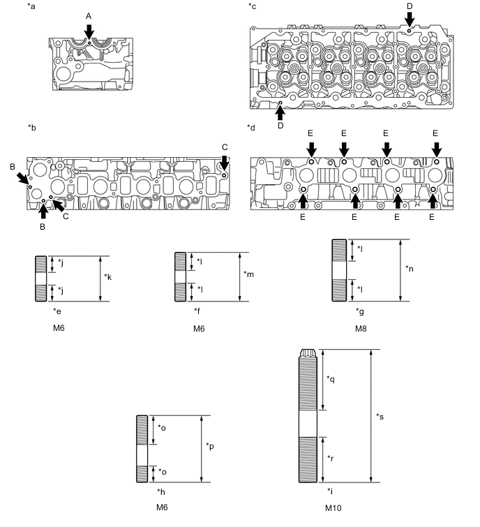
*a Front Side *b Intake Manifold Side *c Cylinder Head Cover Side *d Exhaust Manifold Side *e Stud Bolt A *f Stud Bolt B *g Stud Bolt C *h Stud Bolt D *i Stud Bolt E *j 9.0 mm (0.354 in.) *k 25 mm (0.984 in.) *l 12 mm (0.472 in.) *m 28 mm (1.10 in.) *n 34 mm (1.34 in.) *o 16 mm (0.630 in.) *p 37 mm (1.46 in.) *q 33.5 mm (1.32 in.) *r 25 mm (0.984 in.) *s 60.5 mm (2.38 in.) - -
-
-
INSTALL NO. 1 STRAIGHT SCREW PLUG
Tech Tips
If the No. 1 straight screw plug is corroded, replace it.
-
Apply adhesive to the end of each No. 1 straight screw plug.
Adhesive Toyota Genuine Adhesive 1324, Three Bond 1324 or equivalent -
Using a 6 mm hexagon wrench, install the 4 No. 1 straight screw plugs to the cylinder head sub-assembly.
- Torque:
- 25 N*m { 255 kgf*cm, 18 ft.*lbf }
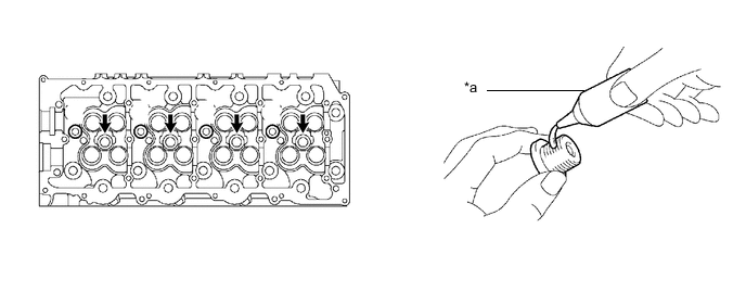
*a Adhesive - -
-
-
INSTALL SEMICIRCULAR PLUG
-
Remove any old seal packing (FIPG material).
-
Apply seal packing to the semicircular plug as shown in the illustration.
Seal packing Toyota Genuine Seal Packing Black, Three Bond 1207B or equivalent Note
-
The semicircular plug must be installed within 3 minutes after applying the seal packing.
-
Prevent seal packing from adhering to the camshaft thrust groove.
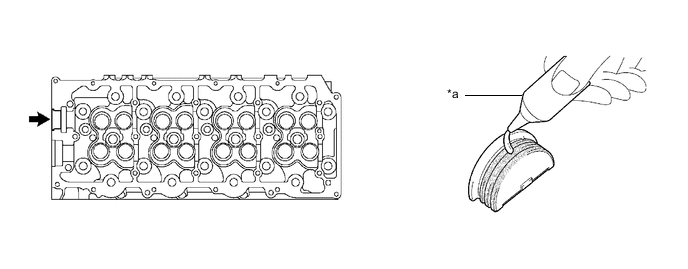
*a Seal Packing - - -
-
Install the semicircular plug to the cylinder head sub-assembly.
-
-
INSTALL INTAKE VALVE STEM OIL SEAL
-
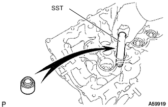
Using SST, push in new intake valve stem oil seals to the calve guide bush.
- SST
- 09201-41020
-
-
INSTALL EXHAUST VALVE STEM OIL SEAL
-
Using SST, push in new exhaust valve stem oil seals to the valve guide bush.
- SST
- 09201-41020
-
-
INSTALL INTAKE VALVE
-
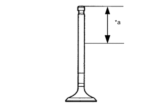
*a 30 mm (1.18 in.) or more Apply a sufficient coat of engine oil to the tip area of the intake valve shown in the illustration.
-
Install the intake valve, valve spring seat, inner compression spring and valve spring retainer to the cylinder head sub-assembly.
-
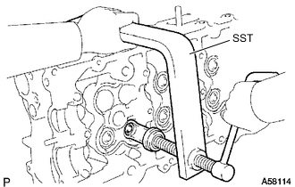
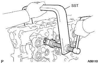
Using SST, compress the inner compression spring and install the 2 valve spring retainer locks to the valve stem.
- SST
- 09202-70020
- 09202-00021
-
Using a plastic-faced hammer, lightly tap the valve stem tip to assure a proper fit.
Note
Be careful not to damage the valve stem tip.
-
-
INSTALL EXHAUST VALVE
-
*a 30 mm (1.18 in.) or more Apply a sufficient coat of engine oil to the tip area of the exhaust valve shown in the illustration.
-
Install the exhaust valve, valve spring seat, inner compression spring and valve spring retainer.
-
Using SST, compress the inner compression spring and install the 2 valve spring retainer locks to the valve stem to the cylinder head sub-assembly.
- SST
- 09202-70020
- 09202-00021
-
Using a plastic-faced hammer, lightly tap the valve stem tip to assure a proper fit.
Note
Be careful not to damage the valve stem tip.
-