ENGINE ASSEMBLY INSTALLATION

CAUTION / NOTICE / HINT
Note
-
When replacing the parts in the following chart (A), replace the No. 1 injection pipe sub-assembly, No. 2 injection pipe sub-assembly, No. 3 injection pipe sub-assembly, No. 4 injection pipe sub-assembly and/or fuel inlet pipe sub-assembly with new ones.
Replaced Parts (A) Pipes Requiring New Replacement
-
Injector assembly (including shuffling the injector assemblies between the cylinders)
-
Common rail assembly
-
Cylinder head sub-assembly
-
No. 1 injection pipe sub-assembly
-
No. 2 injection pipe sub-assembly
-
No. 3 injection pipe sub-assembly
-
No. 4 injection pipe sub-assembly
-
Supply pump assembly
-
Common rail assembly
-
Cylinder block sub-assembly
-
Cylinder head sub-assembly
-
Cylinder head gasket
-
Timing Gear Case Assembly
Fuel inlet pipe sub-assembly -
-
After removing the No. 1 injection pipe sub-assembly, No. 2 injection pipe sub-assembly, No. 3 injection pipe sub-assembly, No. 4 injection pipe sub-assembly and fuel inlet pipe sub-assembly, clean them with a brush and compressed air.
PROCEDURE
-
INSTALL FRONT ENGINE MOUNTING INSULATOR
-
Install the 2 front engine mounting insulators to the 2 front engine mounting brackets with the 2 nuts.
- Torque:
- 64 N*m { 653 kgf*cm, 47 ft.*lbf }
-
-
INSTALL ENGINE WIRE
-
Install the engine wire to the engine assembly.
-
-
INSTALL ENGINE HANGER
-
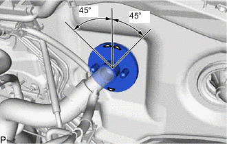
REMOVE ENGINE FROM ENGINE STAND
Note
-
Pay attention to the angle of the sling device as the engine assembly or engine hangers may be damaged or deformed if the angle is incorrect.
-
With the exception of installing the engine assembly to an engine stand or removing the engine assembly from an engine stand, do not perform any work on the engine assembly while it is suspended, as doing so is dangerous.
-
Attach an engine sling device and hang the engine assembly with a chain block.
-
Remove the engine assembly from the engine stand.
-
-
INSTALL ENGINE ASSEMBLY
-
Slowly lower the engine assembly into the engine compartment.
-
Install the engine assembly to the body with the 4 bolts and 4 nuts.
- Torque:
- 42 N*m { 428 kgf*cm, 31 ft.*lbf }
Tech Tips
-
Make sure to tighten the side with the nut.
-
When installing a bolt with a claw (stopper), make sure that the claw (stopper) does not damage the body of the vehicle.
-
Remove the 2 bolts, No. 1 engine hanger upper and No. 2 engine hanger.
-
-
INSTALL REAR END PLATE
-
Install the rear end plate to the cylinder block sub-assembly with the bolt.
- Torque:
- 8.0 N*m { 82 kgf*cm, 71 in.*lbf }
-
-
INSTALL FLYWHEEL SUB-ASSEMBLY
-
Clean the bolt holes.
-
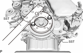
Using SST, hold the crankshaft pulley sub-assembly.
- SST
- 09213-58014 ( 91551-80840 )
- 09330-00021
-
Install the flywheel sub-assembly to the crankshaft to the crankshaft with the 8 bolts.
- Torque:
- 178 N*m { 1815 kgf*cm, 131 ft.*lbf }
Note
Do not start the engine for at least 1 hour after installation.
-
-
INSTALL CLUTCH DISC ASSEMBLY
-
INSTALL CLUTCH COVER ASSEMBLY
-
INSPECT AND ADJUST CLUTCH COVER ASSEMBLY
-
INSTALL MANUAL TRANSMISSION UNIT ASSEMBLY
-
INSTALL PROPELLER WITH CENTER BEARING SHAFT ASSEMBLY
-
INSTALL FRONT EXHAUST PIPE ASSEMBLY
-
CONNECT COOLER COMPRESSOR ASSEMBLY
-
Connect the cooler compressor assembly to the No. 1 compressor mounting bracket with the 4 bolts.
- Torque:
- 24.5 N*m { 250 kgf*cm, 18 ft.*lbf }
-
-
CONNECT PRESSURE FEED TUBE ASSEMBLY
-
Using a 17 mm union nut wrench, connect the pressure feed tube assembly to the vane pump assembly.
- Torque:
- Specified tightening torque
- 44 N*m { 449 kgf*cm, 32 ft.*lbf }
Tech Tips
-
Calculate the torque wrench reading when changing the fulcrum length of the torque wrench.
-
When using a union nut wrench (fulcrum length of 30 mm (1.18 in.)) + torque wrench (fulcrum length of 380 mm (15.0 in.)): 40.8 N*m (416 kgf*cm, 30 ft.*lbf)
-
Connect the oil reservoir to pump hose to the vane pump assembly, and slide the clamp to secure the hose.
-
-
INSTALL BATTERY TRAY
-
INSTALL BATTERY
-
INSTALL BATTERY CLAMP SUB-ASSEMBLY
-
Install the battery clamp sub-assembly to the battery with the 2 nuts.
- Torque:
- 5.4 N*m { 55 kgf*cm, 48 in.*lbf }
-
-
CONNECT WIRE HARNESS
-
Connect the engine room main wire to the battery positive cable with the nut.
- Torque:
- 7.1 N*m { 72 kgf*cm, 63 in.*lbf }
-
Attach the clamp and connect the No. 2 engine wire with the 2 bolts.
- Torque:
- 14 N*m { 143 kgf*cm, 10 ft.*lbf }
-
Connect the 2 connectors to the engine room relay block sub-assembly.
-
Connect the wire to wire to the engine room relay block sub-assembly with the nut.
- Torque:
- 12.5 N*m { 127 kgf*cm, 9 ft.*lbf }
-
Attach the 2 clips and install the No. 1 relay block cover side to the engine room relay block sub-assembly.
-
Attach the 3 clips and install the No. 1 relay block cover upper to the engine room relay block sub-assembly.
-
-
CONNECT UNION TO CONNECTOR TUBE HOSE
-
Connect the union to connector tube hose to the No. 1 hose to hose tube, and slide the clamp to secure the hose.
-
-
CONNECT FUEL HOSE
-
Connect the 2 fuel hoses to the No. 2 nozzle leakage pipe assembly and fuel supply pump assembly, and slide the 2 clamps to secure the hose.
-
-
CONNECT WATER HOSE SUB-ASSEMBLY
-
Connect the water hose sub-assembly to the water outlet and heater pipe, and slide the 2 clamps to secure the 2 hoses.
-
-
INSTALL AIR CLEANER CASE SUB-ASSEMBLY
-
INSTALL AIR CLEANER FILTER ELEMENT SUB-ASSEMBLY
-
INSTALL AIR CLEANER CAP AND HOSE
-
CONNECT ENGINE WIRE
-
Pass the engine wire into the cabin.
-
Attach the grommet to the body.
Tech Tips
Make sure the direction of grommet is shown in the illustration.
-
Connect the 3 connectors to the injector driver.
-
Install the ECM.
-
-
INSTALL GLOVE COMPARTMENT DOOR ASSEMBLY
-
INSTALL NO. 1 INTAKE PIPE
-
Connect the pipe (with the 2 air hoses) and install the bolt.
- Torque:
- 20 N*m { 204 kgf*cm, 15 ft.*lbf }
-
Tighten the 2 clamps.
-
Connect the vacuum hose to the gas filter.
-
Connect the manifold absolute pressure sensor connector.
-
-
INSTALL RADIATOR ASSEMBLY
-
INSTALL HOOD SUB-ASSEMBLY
-
Install the hood sub-assembly to the 2 hood hinge assemblies with the 4 bolts.
- Torque:
- 13 N*m { 133 kgf*cm, 10 ft.*lbf }
-
Connect the washer nozzle hose to the hood sub-assembly.
-
-
ADD POWER STEERING FLUID
-
ADD MANUAL TRANSMISSION OIL
-
ADD ENGINE OIL
-
CONNECT CABLE TO NEGATIVE BATTERY TERMINAL
Note
When disconnecting the cable, some systems need to be initialized after the cable is reconnected.
-
BLEED AIR FROM FUEL SYSTEM
-
ADD ENGINE COOLANT
-
BLEED AIR FROM POWER STEERING SYSTEM
-
INSPECT POWER STEERING FLUID LEVEL
-
PERFORM REGISTRATION
-
Perform registration of the injector compensation codes.
-
Perform pilot quantity learning.
-
-
INSPECT FOR COOLANT LEAK
-
INSPECT FOR OIL LEAK
-
INSPECT FOR EXHAUST GAS LEAK
-
INSPECT FOR FUEL LEAK
-
CHECK ENGINE IDLE SPEED AND MAXIMUM SPEED
-
INSPECT ENGINE OIL LEVEL
-
INSTALL NO. 2 ENGINE UNDER COVER
- Torque:
- 28 N*m { 286 kgf*cm, 21 ft.*lbf }
-
INSTALL NO. 1 ENGINE UNDER COVER ASSEMBLY
- Torque:
- for M6 bolt
- 11.5 N*m { 117 kgf*cm, 8 ft.*lbf }
- for M8 bolt
- 28 N*m { 286 kgf*cm, 21 ft.*lbf }