CYLINDER HEAD REASSEMBLY

PROCEDURE
-
INSTALL STUD BOLT
Note
If a stud bolt is deformed or the threads are damaged, replace it.
-
Using an E6 "TORX" socket wrench, install the stud bolts labeled A to the cylinder head sub-assembly.
- Torque:
- for stud bolt A
- 6.0 N*m { 61 kgf*cm, 53 in.*lbf }
-
Install the stud bolts labeled B to the cylinder head sub-assembly.
- Torque:
- for stud bolt B
- 10 N*m { 102 kgf*cm, 7 ft.*lbf }
-
Using an E10 "TORX" socket wrench, install the stud bolts labeled C and D to the cylinder head sub-assembly.
- Torque:
- for stud bolt C
- 19 N*m { 194 kgf*cm, 14 ft.*lbf }
- for stud bolt D
- 20 N*m { 204 kgf*cm, 15 ft.*lbf }
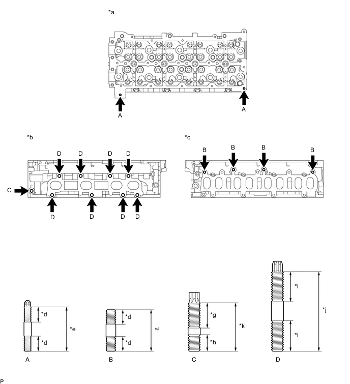
*a Cylinder Head Cover Sub-assembly Side *b Exhaust Manifold Side *c Intake Manifold Side *d 12 mm (0.472 in.) *e 37 mm (1.46 in.) *f 34 mm (1.34 in.) *g 23 mm (0.906 in.) *h 15 mm (0.591 in.) *i 25 mm (0.984 in.) *j 65 mm (2.56 in.) *k 40 mm (1.57 in.) - -
-
-
INSTALL NO. 1 STRAIGHT SCREW PLUG WITH HEAD
-
Using a 6 mm hexagon wrench, install 4 new No. 1 straight screw plug with heads to the cylinder head sub-assembly.
- Torque:
- 25 N*m { 255 kgf*cm, 18 ft.*lbf }
-
-
INSTALL VALVE SPRING SEAT
-
Install the valve spring seats to the cylinder head sub-assembly.
-
-
INSTALL VALVE STEM OIL SEAL
-
Apply a light coat of engine oil to new valve stem oil seals.
-
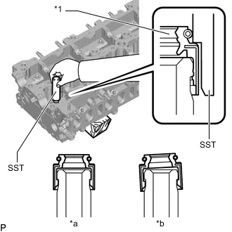
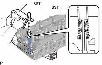
*1 Valve Stem Oil Seal *a CORRECT *b INCORRECT Using SST, push in the intake valve stem oil seals and exhaust valve stem oil seals to the valve guide bush.
- SST
- 09201-41020
Note
Failure to use SST will cause the valve stem oil seal to be damaged or improperly seated.
-
-
INSTALL INTAKE VALVE
-
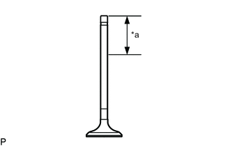
*a 30 mm (1.18 in.) or more Apply plenty of engine oil to the tip area of the intake valve shown in the illustration.
-
Install the intake valve, valve compression spring and valve spring retainer to the cylinder head sub-assembly.
Note
Install the same parts in the same combination to their original locations.
-
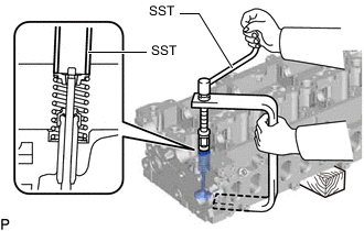
Using SST and wooden blocks, compress the valve compression spring and install the valve spring retainer locks to the valve spring retainer.
- SST
- 09202-70020
- 09202-00021
-
Using a plastic-faced hammer, lightly tap the intake valve stem tip to ensure a proper fit.
Note
Be careful not to damage the valve spring retainer.
-
-
INSTALL EXHAUST VALVE
-

*a 30 mm (1.18 in.) or more Apply plenty of engine oil to the tip area of the exhaust valve shown in the illustration.
-
Install the exhaust valve, valve compression spring and valve spring retainer to the cylinder head sub-assembly.
Note
Install the same parts in the same combination to their original locations.
-
Using SST and wooden blocks, compress the valve compression spring and install the valve spring retainer locks to the valve spring retainer.
- SST
- 09202-70020
- 09202-00021
-
Using a plastic-faced hammer, lightly tap the exhaust valve stem tip to ensure a proper fit.
Note
Be careful not to damage the valve spring retainer.
-
-
INSTALL VALVE STEM CAP
-
Apply a light coat of engine oil to the valve stem caps.
-
Install the 16 valve stem caps to the cylinder head sub-assembly.
Note
-
Install the valve stem cap at the same place it was removed from.
-
Do not drop the valve stem caps into the cylinder head sub-assembly.
-
-