EXHAUST MANIFOLD INSTALLATION
PROCEDURE
-
INSTALL AIR FUEL RATIO SENSOR (for Bank 2 Sensor 1)
-
INSTALL EXHAUST MANIFOLD SUB-ASSEMBLY LH
-
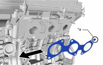
*a Oval Shape 
Forward Install a new gasket to the cylinder head LH with the oval shape facing rearward.
Note
Make sure the gasket is installed facing the proper direction.
-
Install the exhaust manifold sub-assembly LH with 6 new nuts.
- Torque:
- 21 N*m { 214 kgf*cm, 15 ft.*lbf }
-
Connect the air fuel ratio sensor connector.
-
-
INSTALL NO. 2 MANIFOLD STAY
-
Install the No. 2 manifold stay with the 3 bolts.
- Torque:
- 40 N*m { 408 kgf*cm, 30 ft.*lbf }
-
-
INSTALL AIR FUEL RATIO SENSOR (for Bank 1 Sensor 1)
-
INSTALL EXHAUST MANIFOLD SUB-ASSEMBLY RH
-
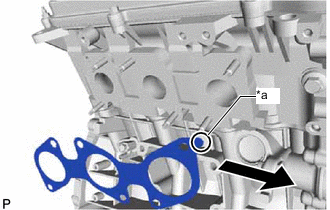
*a Oval Shape Forward Install a new gasket to the cylinder head sub-assembly RH with the oval shape facing forward.
Note
Make sure the gasket is installed facing the proper direction.
-
Install the exhaust manifold sub-assembly RH with 6 new nuts.
- Torque:
- 21 N*m { 214 kgf*cm, 15 ft.*lbf }
-
Connect the air fuel ratio sensor connector.
-
-
INSTALL MANIFOLD STAY
-
Install the manifold stay with the 3 bolts.
- Torque:
- 40 N*m { 408 kgf*cm, 30 ft.*lbf }
-
-
INSTALL FRONT EXHAUST PIPE ASSEMBLY
-
Install the front exhaust pipe assembly to the No. 1 exhaust pipe support.
-
Using a wire brush, remove any foreign matter from the gasket installation surface.
-
Install a new gasket to the end of the front exhaust pipe assembly that connects to the exhaust manifold sub-assembly RH.
Note
Do not reuse the gasket.
-
Connect the front exhaust pipe assembly to the exhaust manifold sub-assembly RH with the 2 new nuts.
- Torque:
- 54.3 N*m { 554 kgf*cm, 40 ft.*lbf }
-
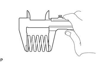
Using a vernier caliper, measure the free length of the compression spring.
Minimum length 40 mm (1.57 in.) If the free length is less than the minimum, replace the compression spring.
-
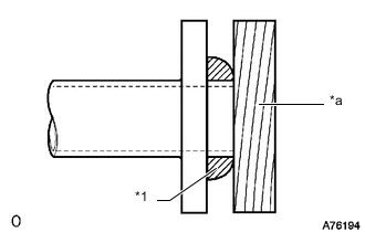
*1 Gasket *a Wooden Block Using a plastic-faced hammer and wooden block, tap on a new gasket until its surface is flush with the front exhaust pipe assembly.
Note
-
Be sure to install the gasket so that it faces the correct direction.
-
Do not reuse the gasket.
-
Do not damage the gasket.
-
When connecting the tail exhaust pipe assembly, do not push in the gasket with the tail exhaust pipe assembly.
-
-
Connect the front exhaust pipe assembly to the tail exhaust pipe assembly with the 2 compression springs and 2 bolts. Alternately tighten the bolts in several passes.
- Torque:
- 43 N*m { 438 kgf*cm, 32 ft.*lbf }
-
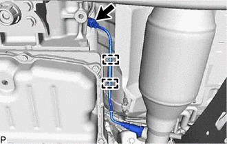
Connect the heated oxygen sensor connector.
-
Attach the 2 clamps.
-
-
INSTALL FRONT NO. 2 EXHAUST PIPE ASSEMBLY
-
INSTALL FRONT PROPELLER SHAFT ASSEMBLY (for 4WD)
-
for TSAM Made
-
for except TSAM Made
-
-
INSPECT FOR EXHAUST GAS LEAK
If gas is leaking, tighten the areas necessary to stop the leak. Replace damaged parts as necessary.
-
INSTALL FRONT FENDER SEAL RH
-
INSTALL FRONT FENDER SEAL LH
-
INSTALL FRONT UPPER FENDER APRON SEAL RH
-
INSTALL FRONT UPPER FENDER APRON SEAL LH