INTAKE MANIFOLD INSTALLATION
PROCEDURE
-
INSTALL STUD BOLT
Note
If a stud bolt is deformed or its threads are damaged, replace it.
-
Using an E7 "TORX" socket wrench, install the 2 stud bolts to the intake manifold.
- Torque:
- 8.0 N*m { 82 kgf*cm, 71 in.*lbf }
-
-
INSTALL INTAKE MANIFOLD
-
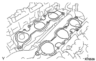
Set 2 new gaskets on each cylinder head.
Note
-
Align the port holes of the gasket and cylinder head.
-
Make sure the gaskets are installed facing the proper direction.
-
-
Set the intake manifold on the cylinder heads.
-
Install and uniformly tighten the 10 bolts in several passes.
- Torque:
- 26 N*m { 265 kgf*cm, 19 ft.*lbf }
Tech Tips
Tighten the inner installation bolts of the intake manifold before tightening the outer bolts.
-
-
INSTALL FUEL DELIVERY PIPE SUB-ASSEMBLY
-
CONNECT NO. 2 FUEL PIPE SUB-ASSEMBLY
-
CONNECT NO. 1 FUEL PIPE SUB-ASSEMBLY
-
INSTALL INTAKE AIR SURGE TANK
NOTICE Do not apply oil to the bolts and nuts listed below: Oil Application Prohibited Bolts for surge tank and intake manifold Nuts for surge tank and intake manifold
-
Install a new gasket to the intake air surge tank.
-
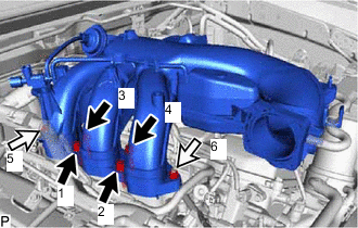

Bolt 
Nut Using an 8 mm hexagon wrench, install the intake air surge tank with the 4 bolts and 2 nuts. Tighten the bolts and nuts in the order shown in the illustration.
- Torque:
- 28 N*m { 286 kgf*cm, 21 ft.*lbf }
-
Install the No. 2 surge tank stay with the 2 bolts.
- Torque:
- 21 N*m { 214 kgf*cm, 15 ft.*lbf }
-
Install the No. 1 surge tank stay with the 2 bolts.
- Torque:
- 21 N*m { 214 kgf*cm, 15 ft.*lbf }
-
Install the oil baffle plate with the bolt.
- Torque:
- 9.0 N*m { 92 kgf*cm, 80 in.*lbf }
-
Install the throttle body bracket with the 2 bolts.
- Torque:
- 21 N*m { 214 kgf*cm, 15 ft.*lbf }
-
Connect the water hose sub-assembly to the intake air surge tank with the 2 bolts.
- Torque:
- 5.4 N*m { 55 kgf*cm, 48 in.*lbf }
-
Attach the 2 wire harness clamps.
-
Connect the purge line hose to the intake air surge tank, and slide the clip to secure the hose.
-
Connect the No. 1 PCV hose to the intake air surge tank, and slide the clip to secure the hose.
-
Attach the 2 wire harness clamps and connect the connector.
-
Connect the connector and attach the wire harness clamp.
-
Connect the fuel vapor feed hose to the purge VSV, and slide the clip to secure the hose.
-
Connect the throttle body with motor connector.
-
Connect the No. 5 water by-pass hose to the throttle body with motor assembly, and slide the clip to secure the hose.
-
Connect the No. 4 water by-pass hose to the throttle body with motor assembly, and slide the clip to secure the hose.
-
-
INSTALL V-BANK COVER BRACKET
-
Install the V-bank cover bracket with the 2 bolts.
- Torque:
- 9.0 N*m { 92 kgf*cm, 80 in.*lbf }
-
-
INSTALL AIR CLEANER CAP SUB-ASSEMBLY WITH NO. 1 AIR CLEANER HOSE
-
ADD ENGINE COOLANT
-
INSPECT FOR COOLANT LEAK
-
INSPECT FOR FUEL LEAK
-
INSTALL V-BANK COVER