EMISSION CONTROL SYSTEM SYSTEM DIAGRAM
-
EMISSION CONTROL AND EVAP CONTROL SYSTEM ILLUSTRATION
To reduce HC emissions, the following occurs. First, evaporated fuel in the fuel tank is absorbed by the canister's active carbon. Then, when the vehicle is being driven, the fuel in the canister and the air are routed into the intake manifold for combustion.
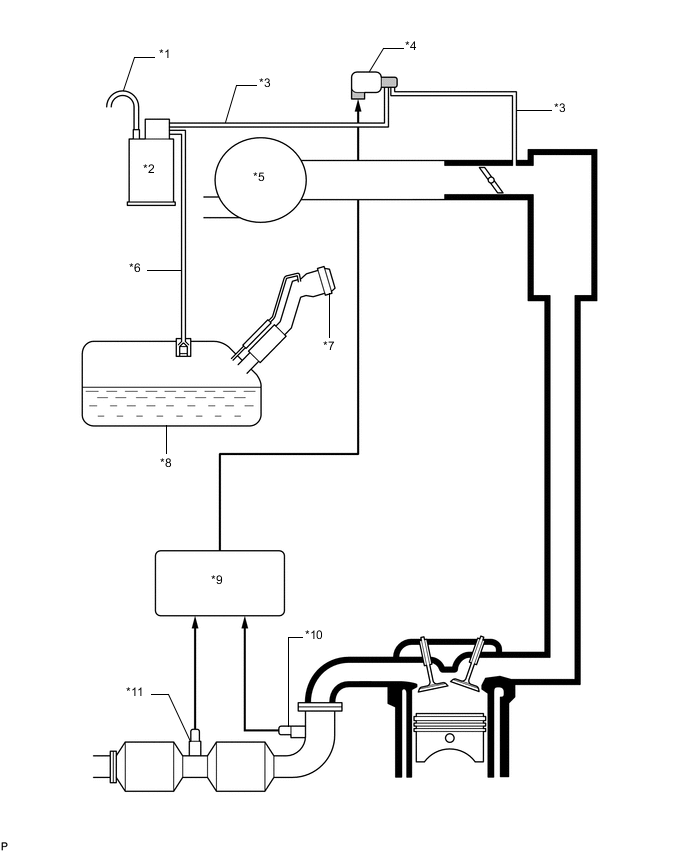
*1 Air Inlet Line *2 Canister *3 Purge Line *4 Purge VSV *5 Air Cleaner Assembly *6 Vent Line *7 Fuel Tank Cap Assembly *8 Fuel Tank Assembly *9 ECM *10 Air Fuel Ratio Sensor *11 Heated Oxygen Sensor - - -
SECONDARY AIR INJECTION SYSTEM ILLUSTRATION (w/ Secondary Air Injection System)
During a cold engine start, this system purifies the catalyst exhaust fumes by applying air pressure to the air hose, exhaust manifold and cylinder head exhaust port.
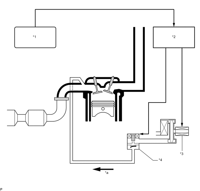
*1 ECM *2 Air Injection Control Driver *3 Air Pump Assembly *4 Air Switching Valve Assembly *a Air - - -
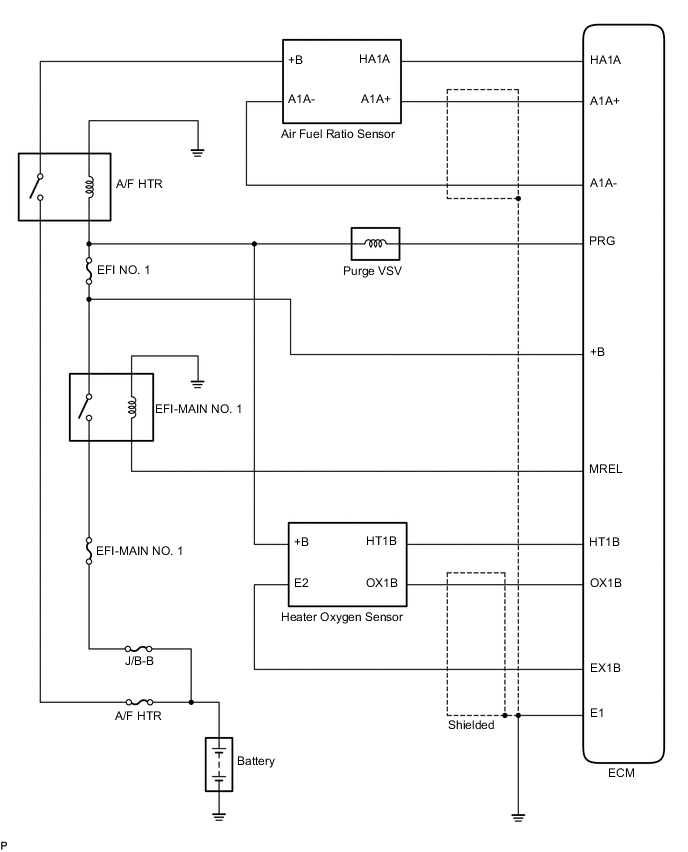
EMISSION CONTROL AND EVAP CONTROL SYSTEM WIRING DIAGRAM
-
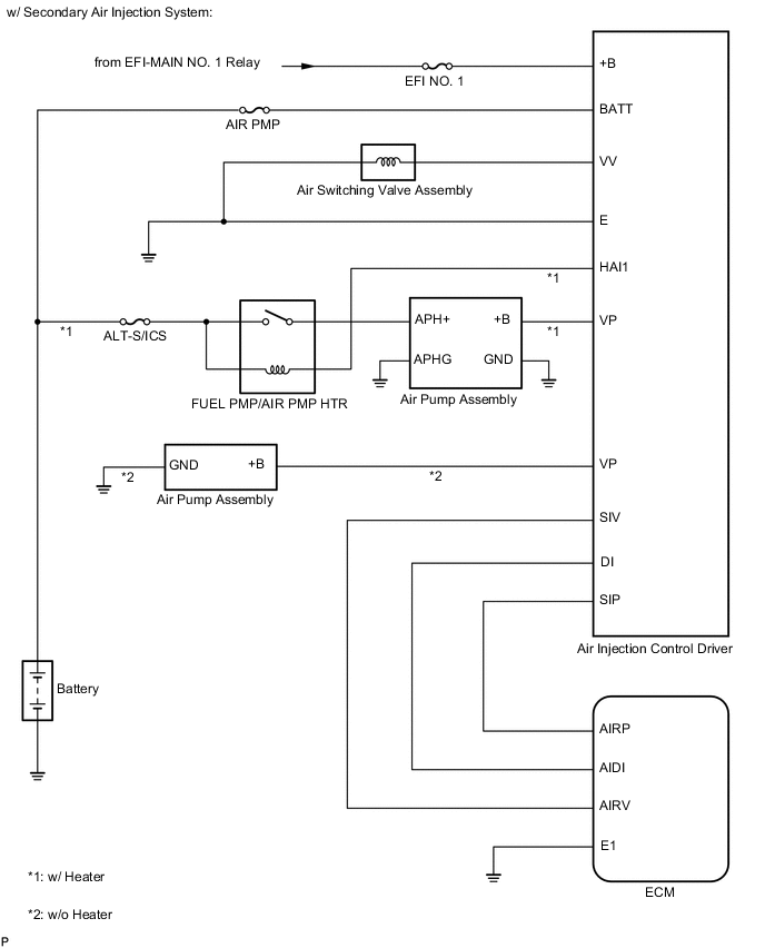
SECONDARY AIR INJECTION SYSTEM WIRING DIAGRAM (w/ Secondary Air Injection System)