CYLINDER HEAD INSPECTION

PROCEDURE
-
CLEAN CYLINDER HEAD
-
Using a gasket scraper, remove all the gasket material from the cylinder block sub-assembly contact surface.
Note
Be careful not to scratch the cylinder block sub-assembly contact surface.
-
Using a wire brush, remove all the carbon from the combustion chambers.
Note
Be careful not to scratch the combustion chambers.
-
Using a valve guide bushing brush and solvent, clean all the valve guide bushes.
-
Using a soft brush and solvent, thoroughly clean the cylinder head.
-
-
INSPECT CYLINDER HEAD
-
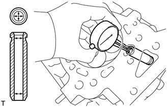
Using a precision straightedge and feeler gauge, measure the warpage of the contact surfaces of the cylinder block and manifolds.
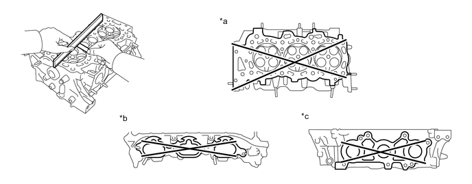
*a Cylinder Block Side *b Intake Manifold Side *c Exhaust Manifold Side - - Standard Warpage Item Specified Condition Cylinder block side 0.05 mm (0.00197 in.) Intake manifold side 0.08 mm (0.00315 in.) Exhaust manifold side 0.05 mm (0.00197 in.) Maximum Warpage Item Specified Condition Cylinder block side 0.10 mm (0.00394 in.) Intake manifold side Exhaust manifold side If the warpage is more than the maximum, replace the cylinder head.
-
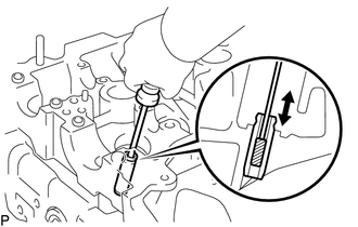
Using a dye penetrant, check the intake ports, exhaust ports and cylinder surface for cracks.
If there are cracks, replace the cylinder head.
-
-
INSPECT INNER COMPRESSION SPRING
-
Using a vernier caliper, measure the free length of the inner compression spring.
Standard free length 47.8 mm (1.88 in.) If the free length is not as specified, replace the inner compression spring.
-
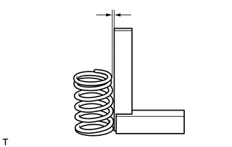
Using a steel square, measure the deviation of the inner compression spring.
Maximum deviation 2.0 mm (0.0787 in.) If the deviation is more than the maximum, replace the inner compression spring.
-
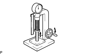
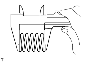
Using a spring tester, measure the tension of the inner compression spring at the standard installed length.
Standard tension 186 to 206 N (19 to 21 kgf, 41.8 to 46.3 lbf) at 36.2 mm (1.43 in.) If the tension is not as specified, replace the inner compression spring.
-
-
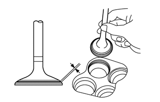
CLEAN VALVE
-
Using a gasket scraper, chip off any carbon from the valve head.
-
Using a wire brush, thoroughly clean the valve.
-
-
INSPECT VALVE
-
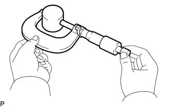
Using a micrometer, measure the diameter of the valve stem.
Standard Valve Stem Diameter Item Specified Condition Intake valve 5.470 to 5.485 mm (0.2154 to 0.2159 in.) Exhaust valve 5.465 to 5.480 mm (0.2152 to 0.2157 in.) -
Inspect the valve face angle.
-
Grind the valve enough to remove pits and carbon.
-
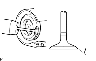
Check that the valve is ground to the correct valve face angle.
Standard valve face angle 44.5°
-
-
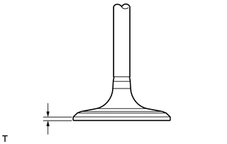
Using a vernier caliper, measure the valve head margin thickness.
Standard margin thickness 1.0 mm (0.0394 in.) Minimum margin thickness 0.5 mm (0.0197 in.) If the margin thickness is less than the minimum, replace the valve.
-
Using a vernier caliper, measure the overall length of the valve.
Standard Overall Length Item Specified Condition Intake valve 106.95 mm (4.21 in.) Exhaust valve 105.80 mm (4.17 in.) Minimum Overall Length Item Specified Condition Intake valve 106.40 mm (4.19 in.) Exhaust valve 105.30 mm (4.15 in.) If the overall length is less than the minimum, replace the valve.
-
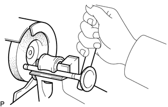
Check the surface of the valve stem tip for wear.
Note
Do not grind the valve so it becomes shorter than the minimum overall length.
If the valve stem tip is worn, resurface the tip with a grinder or replace the valve.
-
-
INSPECT VALVE GUIDE BUSH OIL CLEARANCE
-
Using a caliper gauge, measure the inside diameter of the guide bush.
Standard bush inside diameter 5.51 to 5.53 mm (0.217 to 0.218 in.) -
Subtract the valve stem diameter measurement from the guide bush inside diameter measurement.
Standard Oil Clearance Item Specified Condition Intake side 0.025 to 0.060 mm (0.000984 to 0.00236 in.) Exhaust side 0.030 to 0.065 mm (0.00118 to 0.00256 in.) Maximum Oil Clearance Item Specified Condition Intake side 0.08 mm (0.00315 in.) Exhaust side 0.10 mm (0.00394 in.) If the oil clearance is more than the maximum, replace the valve and valve guide bush.
-
-
CLEAN VALVE SEAT
-
Using a 45° carbide cutter, resurface the valve seats.
-
Clean the valve seats.
-
-
INSPECT VALVE SEAT
-
Apply a light coat of Prussian blue to the valve face.
-
Lightly press the valve face against the valve seat.
Note
Do not rotate the valve.
-
Check the valve face and valve seat by using the following procedure.
-
Check that Prussian blue appears around the entire valve face. If not, replace the valve.
-
If Prussian blue appears around the entire valve seat, the guide and valve face are concentric. If not, resurface the valve seat.
-
Check that the seat contacts the middle of the valve face with the width below.
Standard width 1.0 to 1.4 mm (0.0394 to 0.0551 in.)
-
-
-
INSPECT CAMSHAFT OIL CLEARANCE
-
INSPECT CAMSHAFT THRUST CLEARANCE
-
INSPECT VALVE LIFTER
-
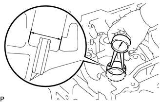
Using a micrometer, measure the valve lifter diameter.
Standard valve lifter diameter 30.966 to 30.976 mm (1.219 to 1.220 in.) If the result is not as specified, replace the valve lifter.
-
Using a caliper gauge, measure the lifter bore diameter of the cylinder head.
Standard lifter bore diameter 31.009 to 31.025 mm (1.220 to 1.221 in.) -
Subtract the valve lifter diameter from the lifter bore diameter of the cylinder head.
Standard oil clearance 0.033 to 0.059 mm (0.00130 to 0.00232 in.) Maximum oil clearance 0.08 mm (0.00315 in.) If the oil clearance is more than the maximum, replace the valve lifter.
If necessary, replace the cylinder head.
-