ENGINE ASSEMBLY INSTALLATION
PROCEDURE
-
INSTALL ENGINE HANGER
-
REMOVE ENGINE ASSEMBLY FROM ENGINE STAND
Note
-
Pay attention to the angle of the sling device as the engine assembly or engine hangers may be damaged or deformed if the angle is incorrect.
-
With the exception of installing the engine assembly to an engine stand or removing the engine assembly from an engine stand, do not perform any work on the engine while it is suspended, as doing so is dangerous.
-
Attach the engine sling device and hang the engine assembly with the chain block.
-
Remove the engine assembly from the engine stand.
-
-
INSTALL ENGINE ASSEMBLY
-
Slowly lower the engine assembly into the engine compartment.
-
Install the engine assembly to the body with the 4 bolts and 4 nuts.
- Torque:
- 42 N*m { 428 kgf*cm, 31 ft.*lbf }
Tech Tips
-
Make sure to tighten the side with the nut.
-
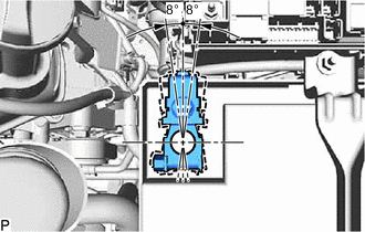
When installing a bolt with a claw (stopper), make sure to install the bolt with the claw (stopper) as shown in the illustration so that a clearance is maintained between the claw (stopper) and the intermediate shaft.
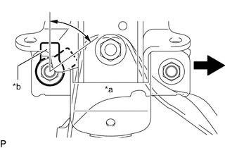
*a Front Engine Mounting Insulator
(LH Side)
*b Claw (Stopper) 
Front -
Remove the 4 bolts, No. 1 engine hanger and No. 2 engine hanger.
-
-
INSTALL DRIVE PLATE AND RING GEAR SUB-ASSEMBLY
-
INSTALL AUTOMATIC TRANSMISSION ASSEMBLY
-
for 4WD:
-
for Pre-Runner:
-
-
INSTALL DRIVE PLATE AND TORQUE CONVERTER ASSEMBLY SETTING BOLT
-
INSTALL PROPELLER SHAFT WITH CENTER BEARING ASSEMBLY (for 4WD)
-
for TSAM Made:
-
for TMT Made:
-
for TMMIN Made:
-
-
INSTALL PROPELLER SHAFT WITH CENTER BEARING ASSEMBLY (for Pre-Runner)
-
for TSAM Made:
-
for TMT Made:
-
for TMMIN Made:
-
-
INSTALL PROPELLER SHAFT GUARD
-
INSTALL FRONT DIFFERENTIAL CARRIER ASSEMBLY (for 4WD)
-
INSTALL POWER STEERING LINK ASSEMBLY (for 4WD)
-
CONNECT STEERING SLIDING YOKE (for 4WD)
-
INSTALL FRONT DRIVE SHAFT HOLE SNAP RING (for 4WD)
-
INSTALL FRONT DRIVE SHAFT ASSEMBLY LH (for 4WD)
-
INSTALL FRONT DRIVE SHAFT ASSEMBLY RH (for 4WD)
Tech Tips
Use the same procedure described for the LH side.
-
CONNECT FRONT LOWER NO. 1 SUSPENSION ARM SUB-ASSEMBLY LH (for 4WD)
-
CONNECT FRONT LOWER NO. 1 SUSPENSION ARM SUB-ASSEMBLY RH (for 4WD)
Tech Tips
Use the same procedure described for the LH side.
-
CONNECT TIE ROD END SUB-ASSEMBLY LH (for 4WD)
-
CONNECT TIE ROD END SUB-ASSEMBLY RH (for 4WD)
Tech Tips
Use the same procedure described for the LH side.
-
CONNECT FRONT SPEED SENSOR LH (for 4WD)
-
CONNECT FRONT SPEED SENSOR RH (for 4WD)
Tech Tips
Use the same procedure described for the LH side.
-
INSTALL FRONT AXLE SHAFT NUT (for 4WD)
-
INSTALL FRONT AXLE HUB GREASE CAP (for 4WD)
-
INSTALL FRONT PROPELLER SHAFT ASSEMBLY (for 4WD)
-
INSTALL PROPELLER SHAFT GUARD (for 4WD)
-
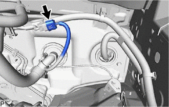
CONNECT NO. 2 FUEL PIPE SUB-ASSEMBLY
-
Connect the No. 2 fuel pipe sub-assembly, and slide the clamp to secure the hose.
-
-
CONNECT NO. 1 FUEL PIPE SUB-ASSEMBLY
-
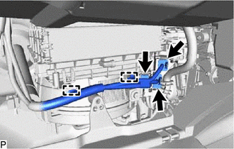
INSTALL WATER HOSE SUB-ASSEMBLY
-
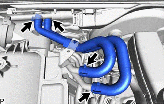
Install the water hose sub-assembly, and slide the 4 clamps to secure the hose.
-
-
CONNECT COOLER COMPRESSOR ASSEMBLY
-
INSTALL GENERATOR ASSEMBLY
-
for 115A Type:
-
for 100A Type:
-
-
CONNECT ENGINE WIRE (for LHD)
-
Connect the 2 connectors to the engine room relay block.
-
Connect the engine wire to the engine room relay block with the nut.
- Torque:
- 12.5 N*m { 127 kgf*cm, 9 ft.*lbf }
-
Attach the 2 claws and install the No. 1 relay block cover side to the engine room relay block.
-
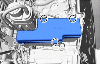
Attach the 3 claws and install the No. 1 relay block cover upper to the engine room relay block.
-
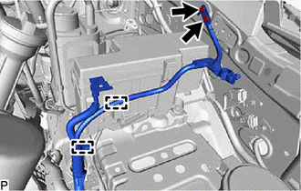
Attach the 2 clamps and connect the No. 2 engine wire with the 2 bolts.
- Torque:
- 14 N*m { 143 kgf*cm, 10 ft.*lbf }
-
Install the battery tray.
-
Install the battery.
-
Install the battery hold down clamp with the 2 nuts.
- Torque:
- 5.4 N*m { 55 kgf*cm, 48 in.*lbf }
-
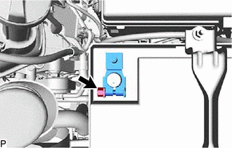
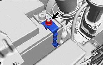
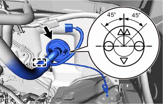
Tighten the nut and install the positive (+) battery terminal.
- Torque:
- 5.35 N*m { 55 kgf*cm, 47 in.*lbf }
Tech Tips
Position the positive (+) battery terminal as shown in the illustration.
-
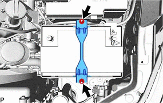
Connect the engine room main wire to the battery positive cable with the nut.
- Torque:
- 7.55 N*m { 77 kgf*cm, 67 in.*lbf }
-
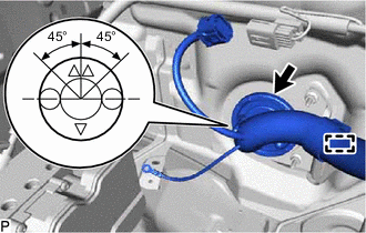
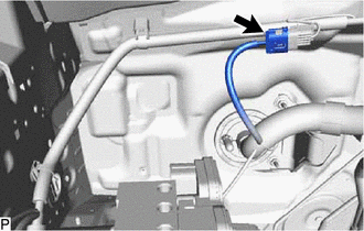
Push the engine wire through the dash panel into the cabin.
Tech Tips
The wire should be within the range shown in the illustration.
-
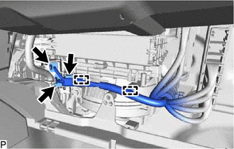
Connect the engine wire and attach the clamp to the bracket.
-
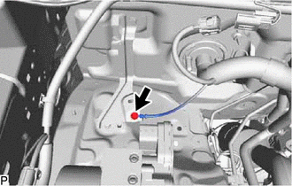
Connect the engine wire with the bolt.
- Torque:
- 7.55 N*m { 77 kgf*cm, 67 in.*lbf }
-
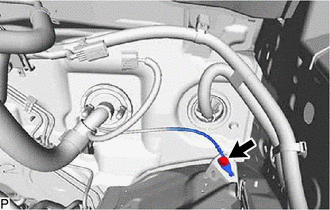
Connect the connector.
-
Attach the 2 clamps and connect the 3 connectors to the instrument panel wire.
-
-
CONNECT ENGINE WIRE (for RHD)
-
Connect the 2 connectors to the engine room relay block.
-
Connect the engine wire to the engine room relay block with the nut.
- Torque:
- 12.5 N*m { 127 kgf*cm, 9 ft.*lbf }
-
Attach the 2 claws and install the No. 1 relay block cover side to the engine room relay block.
-
Attach the 3 claws and install the No. 1 relay block cover upper to the engine room relay block.
-
Attach the 2 clamps and connect the No. 2 engine wire with the 2 bolts.
- Torque:
- 14 N*m { 143 kgf*cm, 10 ft.*lbf }
-
Install the battery tray.
-
Install the battery.
-
Install the battery hold down clamp with the 2 nuts.
- Torque:
- 5.4 N*m { 55 kgf*cm, 48 in.*lbf }
-
Tighten the nut and install the positive (+) battery terminal.
- Torque:
- 5.35 N*m { 55 kgf*cm, 47 in.*lbf }
Tech Tips
Position the positive (+) battery terminal as shown in the illustration.
-
Connect the engine room main wire to the battery positive cable with the nut.
- Torque:
- 7.55 N*m { 77 kgf*cm, 67 in.*lbf }
-
Push the engine wire through the dash panel into the cabin.
Tech Tips
The wire should be within the range shown in the illustration.
-
Connect the engine wire and attach the clamp to the bracket.
-
Connect the engine wire with the bolt.
- Torque:
- 7.55 N*m { 77 kgf*cm, 67 in.*lbf }
-
Connect the connector.
-
Attach the 2 clamps and connect the 3 connectors to the instrument panel wire.
-
-
INSTALL ECM
-
INSTALL GLOVE COMPARTMENT DOOR ASSEMBLY
-
INSTALL NO. 2 INSTRUMENT PANEL UNDER COVER SUB-ASSEMBLY
-
INSTALL FLYWHEEL HOUSING SIDE COVER
-
INSTALL STARTER ASSEMBLY
-
INSTALL EXHAUST MANIFOLD SUB-ASSEMBLY LH
-
INSTALL NO. 2 MANIFOLD STAY
-
INSTALL EXHAUST MANIFOLD SUB-ASSEMBLY RH
-
INSTALL MANIFOLD STAY
-
INSTALL FRONT EXHAUST PIPE ASSEMBLY
-
INSTALL FRONT NO. 2 EXHAUST PIPE ASSEMBLY
-
INSTALL INTAKE AIR SURGE TANK
-
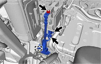
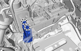
CONNECT VANE PUMP ASSEMBLY
-
Connect the vane pump assembly with the 2 bolts.
- Torque:
- 21 N*m { 214 kgf*cm, 15 ft.*lbf }
Note
Do not hit other parts with the pulley when installing the vane pump.
-
Connect the connector.
-
-
INSTALL RADIATOR ASSEMBLY
-
CONNECT NO. 1 OIL COOLER INLET HOSE
-
CONNECT NO. 1 OIL COOLER OUTLET HOSE
-
INSTALL FAN SHROUD
-
INSTALL RADIATOR RESERVOIR
-
INSTALL RADIATOR HOSE INLET
-
INSTALL RADIATOR HOSE OUTLET
-
INSTALL NO. 1 RADIATOR AIR GUIDE
-
INSTALL AIR CLEANER CASE SUB-ASSEMBLY
-
Install the air cleaner case sub-assembly with the 3 bolts.
- Torque:
- 6.0 N*m { 61 kgf*cm, 53 in.*lbf }
-
Connect the 3 clamps to the air cleaner case sub-assembly.
-
-
INSTALL AIR CLEANER FILTER ELEMENT SUB-ASSEMBLY
-
INSTALL AIR CLEANER CAP SUB-ASSEMBLY WITH NO. 1 AIR CLEANER HOSE
-
INSTALL RADIATOR SIDE DEFLECTOR LH
-
INSTALL RADIATOR SIDE DEFLECTOR RH
Tech Tips
Use the same procedure described for the LH side.
-
INSTALL FRONT UPPER FENDER APRON SEAL LH
-
Install the front upper fender apron seal LH with 6 new clips.
-
-
INSTALL FRONT UPPER FENDER APRON SEAL RH
-
Install the front upper fender apron seal RH with 6 new clips.
-
-
INSTALL FRONT FENDER SEAL LH
-
Install the front fender seal LH with 6 new clips.
-
-
INSTALL FRONT FENDER SEAL RH
-
Install the front fender seal RH with 6 new clips.
-
-
ADD DIFFERENTIAL OIL (for 4WD)
-
INSTALL NO. 3 ENGINE UNDER COVER SUB-ASSEMBLY
- Torque:
- 28 N*m { 286 kgf*cm, 21 ft.*lbf }
-
INSTALL NO. 2 ENGINE UNDER COVER
- Torque:
- 28 N*m { 286 kgf*cm, 21 ft.*lbf }
-
INSTALL NO. 1 ENGINE UNDER COVER ASSEMBLY
- Torque:
- for M6 bolt
- 11.5 N*m { 117 kgf*cm, 8 ft.*lbf }
- for M8 bolt
- 28 N*m { 286 kgf*cm, 21 ft.*lbf }
-
INSTALL HOOD SUB-ASSEMBLY
-
Install the hood sub-assembly to the 2 hood hinge assemblies with the 4 bolts.
- Torque:
- 13 N*m { 133 kgf*cm, 10 ft.*lbf }
-
Connect the washer nozzle hose.
-
Adjust the hood sub-assembly.
-
-
CONNECT CABLE TO NEGATIVE BATTERY TERMINAL
Note
When disconnecting the cable, some systems need to be initialized after the cable is reconnected.
-
ADD ENGINE OIL
-
ADD ENGINE COOLANT
-
INSPECT FOR COOLANT LEAK
-
INSPECT FOR FUEL LEAK
-
INSPECT FOR OIL LEAK
-
INSPECT FOR EXHAUST GAS LEAK
-
INSPECT IGNITION TIMING
-
INSPECT ENGINE IDLE SPEED
-
INSPECT CO/HC
-
INSTALL V-BANK COVER