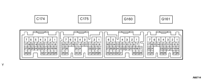
ECD SYSTEM TERMINALS OF ECM
Tech Tips
Each ECM terminal's standard voltage is shown in the table below.
In the table, first follow the information under "Condition".
Look under "Terminal No. (Symbol)" for the terminals to be inspected. The standard voltage between the terminals is shown under "Specified Condition".
Use the illustration above as a reference for the ECM terminals.
| Terminal No. (Symbol) | Wiring Color | Terminal Description | Condition | Specified Condition |
|---|---|---|---|---|
| G161-2 (BATT) - C174-5 (E1) | Y - BR | Battery (for measuring the battery voltage and for the ECM memory) | Always | 11 to 14 V |
| G161-8 (SREL) - C174-5(E1) | LG - BR | GLOW relay | Cranking | 11 to 14 V |
| Idling (engine started and 600 sec. have passed) | 0 to 1.5 V | |||
| G161-10 (MREL) - C174-5(E1) | G - BR | MAIN relay | Ignition switch ON | 11 to 14 V |
| Ignition switch off (2 sec. after ignition switch off) | 0 to 1.5 V | |||
| G161-17 (TC) - C174-5 (E1) | R - BR | Terminal TC of DLC3 | Ignition switch ON | 11 to 14 V |
| G160-25 (SP1) - C174-5 (E1) | V- -BR | Speed signal from combination meter | Ignition switch ON, slowlyrotate wheel | Pulse generation (See waveform 1) |
| G160-6 (STA) - C174-5 (E1) | GR - BR | Starter signal | Cranking | 6 V or more |
| G161-1 (+B) - C174-5 (E1) | L - BR | Power source of ECM | Ignition switch ON | 11 to 14 V |
| G161-11 (IGSW) - C174-5(E1) | GR - BR | Ignition switch | Ignition switch ON | 11 to 14 V |
| G160-9 (STP) - C174-5 (E1) | L - BR | Stop light switch | Brake pedal depressed | 11 to 14 V |
| Brake pedal released | Below 1.5 V | |||
| G160-34(AC1) - C174-5 (E1) | GR - BR | A/C amplifier | A/C switch on (magnetic clutch on) |
Below 1.5 V |
| A/C switch off | 7.5 to 14 V | |||
| G161-9 (ACT) - C174-5 (E1) | LG - BR | A/C amplifier | Ignition switch ON | 11 to 14 V |
| A/C cut performed (driving below 30 km/h (18.6 mph), accelerator pedal fully depressed for 5 sec.) | 0 to 3 V | |||
| G161-20 (VPA) - G161-27(EPA) | W - G | Accelerator pedal position sensor (for engine control) | Ignition switch ON, accelerator pedal released | 0.6 to 1.0 V |
| Ignition switch ON, accelerator pedal depressed | 3.0 to 4.6 V | |||
| G161-28 (VPA2) - G161-29(EPA2) | GR - Y | Accelerator pedal position sensor (for sensor malfunction detection) | Ignition switch ON, accelerator pedal released | 1.4 to 1.8 V |
| Ignition switch ON, accelerator pedal depressed | 3.7 to 5.0 V | |||
| G161-26 (VCPA) - G161-27(EPA) | LG - G | Power source of accelerator pedal position sensor (for VPA) | Ignition switch ON | 4.5 to 5.0 V |
| G161-23 (VCP2) - G161-29(EPA2) | R - Y | Power source of accelerator pedal position sensor (for VPA2) | Ignition switch ON | 4.5 to 5.0 V |
| G160-7 (TACH) - C174-5(E1) | V - BR | Engine speed sensor | Idling | Pulse generation (See waveform 2) |
| G160-10 (ST1-) - C174-5(E1) | GR - BR | Stop light switch | Brake pedal depressed | 0 to 1.5 V |
| Brake pedal released | 7.5 to 14 V | |||
| C175-33 (PIM) - C175-32(EPIM) | L - GR | Manifold absolute pressure sensor | 60 kPa (450 mmHg, 17.7 in.Hg) vacuum applied | 0.2 to 0.8 V |
| 207 kPa (1550 mmHg, 61.0 in.Hg) vacuum applied | 4.2 to 4.8 V | |||
| C175-22 (THA) - C175-30(ETHA) | Y - R | Intake air temperaturesensor | Idling, air intake temp. 0°C (32°F) to 80°C (176°F) | 0.5 to 3.4 V |
| C175-21 (THW) - C175-29(ETHW) | R - B | Engine coolant temperature sensor | Idling, engine coolant temp. 60°C (140°F) to 120°C (248°F) | 0.2 to 1.0 V |
| C175-23 (THF) - C175-31(ETHF) | G - R | Terminal TC of DLC3 | Ignition switch ON | 11 to 14 V |
| C174-29 (DATA) - C174-5(E1) | Y - BR | Injection pump | Within 0.5 sec. after ignition switch ON | Pulse generation |
| C174-28 (CLK) - C174-5 (E1) | L - BR | Injection pump | Within 0.5 sec. after ignition switch ON | Pulse generation |
| C175-15 (THOP) - C174-5(E1) | GR - BR | Throttle open switch | Idling (engine warmed up) | 11 to 14 V |
| Ignition switch ON (once within 5 sec.) | 0 to 3 V | |||
| C174-14 (LU-B) - C174-7(E01) | Y - W-B | Throttle control motor (intake shutter) |
Racing (engine warmed up) | Pulse generation (See waveform 3) |
| C174-15 (LU+B) - C174-7(E01) | R - W-B | Throttle control motor (intake shutter) |
Racing (engine warmed up) | Pulse generation (See waveform 3) |
| C174-16 (LU-A) - C174-7(E01) | W - W-B | Throttle control motor (intake shutter) |
Racing (engine warmed up) | Pulse generation (See waveform 3) |
| C174-17 (LU+A) - C174-7(E01) | GR - W-B | Throttle control motor (intake shutter) |
Racing (engine warmed up) | Pulse generation (See waveform 3) |
| C174-11 (TCV) - C174-7(E01) | R - W-B | Timing control valve | Ignition switch ON | 11 to 14 V |
| Idling | Pulse generation (See waveform 4) |
|||
| C174-2 (SPV+) - C174-5 (E1) | L - BR | Spill control valve | Ignition switch ON | 11 to 14 V |
| Idling | Pulse generation | |||
| C174-1 (SPV-) - C174-5 (E1) | Y - BR | Spill control valve | Idling | Pulse generation (See waveform 5) |
| C175-26 (TDC+) - C175-34(TDC-) | R - G | Crankshaft position sensor | Idling | Pulse generation (See waveform 6) |
| C175-27 (NE+) - C175-35(NE-) | L - Y | Engine speed sensor | Idling | Pulse generation (See waveform 6) |
| G161-25 (CANH) - C174-5(E1) | B - BR | CAN communication line | Ignition switch ON | Pulse generation (See waveform 7) |
| G161-31 (CANL) - C174-5(E1) | W - BR | CAN communication line | Ignition switch ON | Pulse generation (See waveform 8) |
-
Waveform 1
-
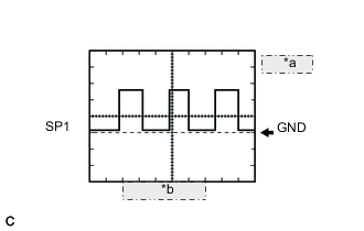
*a 2 V/DIV. *b 20 msec./DIV. Speed signal
ECM TerminalName Between SP1 and E1 Tester Range 2 V/DIV., 20 msec./DIV. Condition Driving at approx. 20 km/h (12.4 mph) Tech Tips
-
As vehicle speed increases, the wavelength becomes shorter.
-
As vehicle speed increases, the waveform's amplitude becomes greater.
-
-
-
Waveform 2
-
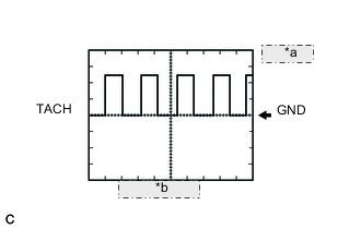
*a 5 V/DIV. *b 20 msec./DIV. Engine speed signal
ECM TerminalName Between TACH and E1 Tester Range 5 V/DIV., 20 msec./DIV. Condition Idling after warming up Tech Tips
As engine speed increases, the wavelength becomes shorter.
-
-
Waveform 3
-
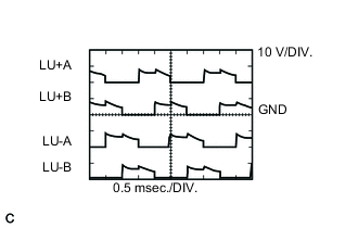
Throttle control motor signals
ECM TerminalName Between LU+A and E01
Between LU-A and E01
Between LU+B and E01
Between LU-B and E01
Tester Range 10 V/DIV., 0.5 msec./DIV. Condition Engine racing
-
-
Waveform 4
-
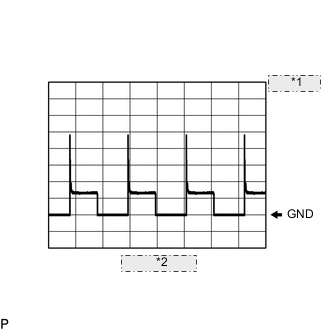
*1 10 V/DIV. *2 20 msec./DIV. Timing control value signal
ECM TerminalName Between TCV and E01 Tester Range 10 V/DIV., 20 msec./DIV. Condition During idling
-
-
Waveform 5
-
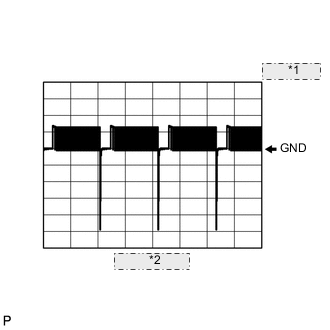
*1 10 V/ DIV. *2 20 msec./DIV. Spill control valve signal
ECM TerminalName Between SPV- and E1 Tester Range 10 V/DIV., 20 msec./DIV. Condition During idling
-
-
Waveform 6
-
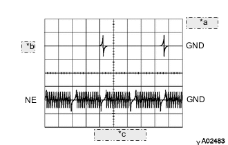
*a 2 V/DIV. *b TDC *c 20 msec./DIV. Crankshaft position sensor and engine speed sensor signals
ECM TerminalName Between TDC+ and TDC-
Between NE+ and NE-
Tester Range 2 V/DIV., 20 msec./DIV. Condition During idling
-
-
Waveform 7
-
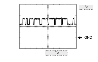
*a 1 V/DIV. *b 10 msec./DIV. CAN Communication Signal
ECM TerminalName Between CANH and E1 Tester Range 1 V/DIV., 10 msec./DIV. Condition Engine stopped, ignition switch ON Tech Tips
The waveform varies depending on the CAN communication signal.
-
-
Waveform 8
-
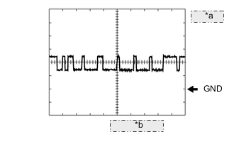
*a 1 V/DIV. *b 10 msec./DIV. CAN Communication Signal
ECM TerminalName Between CANL and E1 Tester Range 1 V/DIV., 10 msec./DIV. Condition Engine stopped, ignition switch ON Tech Tips
The waveform varies depending on the CAN communication signal.
-