ENGINE UNIT REASSEMBLY

CAUTION / NOTICE / HINT
Note
-
When replacing the parts in the following chart (A), replace the No. 1 injection pipe sub-assembly, No. 2 injection pipe sub-assembly, No. 3 injection pipe sub-assembly, No. 4 injection pipe sub-assembly and/or fuel inlet pipe sub-assembly with new ones.
Replaced Parts (A) Pipes Requiring New Replacement
-
Injector assembly (including shuffling the injector assemblies between the cylinders)
-
Common rail assembly
-
Cylinder head sub-assembly
-
No. 1 injection pipe sub-assembly
-
No. 2 injection pipe sub-assembly
-
No. 3 injection pipe sub-assembly
-
No. 4 injection pipe sub-assembly
-
Supply pump assembly
-
Common rail assembly
-
Cylinder block sub-assembly
-
Cylinder head sub-assembly
-
Cylinder head gasket
-
Timing Gear Case Assembly
Fuel inlet pipe sub-assembly -
-
After removing the No. 1 injection pipe sub-assembly, No. 2 injection pipe sub-assembly, No. 3 injection pipe sub-assembly, No. 4 injection pipe sub-assembly and fuel inlet pipe sub-assembly, clean them with a brush and compressed air.
PROCEDURE
-
INSTALL INJECTION PUMP OIL SEAL
-
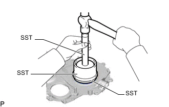
Using SST and a hammer, tap in a new injection pump oil seal until its surface is flush with the timing gear cover edge.
- SST
- 09223-15020
- 09502-12010
- 09950-70010 ( 09951-07100 )
Note
-
Keep the lip free from foreign matter.
-
Do not tap the supply pump oil seal at an angle.
-
Apply MP grease to the lip of the injection pump oil seal.
-
-
INSTALL FRONT CRANKSHAFT OIL SEAL
-
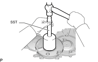
Using SST and a hammer, tap in a new front crankshaft oil seal until its surface is flush with the timing gear cover edge.
- SST
- 09214-76011
Note
-
Keep the lip free from foreign matter.
-
Do not tap the front crankshaft oil seal at an angle.
-
Apply MP grease to the lip of the front crankshaft oil seal.
-
-
INSTALL REAR ENGINE OIL SEAL
-
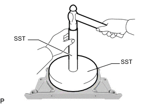
Using SST and a hammer, tap in a new rear engine oil seal until its surface is flush with the rear engine oil seal retainer edge.
- SST
- 09518-36030
- 09950-70010 ( 09951-07100 )
Note
-
Keep the lip free from foreign matter.
-
Do not tap the rear engine oil seal at an angle.
-
Apply MP grease to the lip of the rear engine oil seal.
-
-
INSTALL REAR ENGINE OIL SEAL RETAINER
-
Remove any old seal packing (FIPG material) from the cylinder block sub-assembly.
-
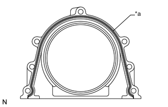
*a Seal Packing Apply seal packing to the places shown in the illustration.
Seal packing Toyota Genuine Seal Packing Black, Three Bond 1207B or equivalent Standard seal diameter 4 mm (0.157 in.) Note
After applying seal packing, install the rear engine oil seal retainer within 3 minutes and tighten the bolts within 15 minutes.
-
Install the rear engine oil seal retainer with the 5 bolts. Alternately tighten the 5 bolts in several passes.
- Torque:
- 13 N*m { 133 kgf*cm, 10 ft.*lbf }
-
-
INSTALL NO. 2 BALANCESHAFT DRIVEN GEAR
-
Mount the No. 2 balanceshaft sub-assembly between aluminum plates in a vise.
Note
Be careful not to damage the No. 2 balanceshaft sub-assembly.
-
Align the balanceshaft knock pin with the knock pin hole. Then install the balanceshaft thrust washer and No. 2 balanceshaft driven gear to the No. 2 balanceshaft sub-assembly.
-
Install the bolt.
- Torque:
- 36 N*m { 367 kgf*cm, 27 ft.*lbf }
-
-
INSTALL NO. 2 BALANCESHAFT SUB-ASSEMBLY
-
Install the No. 2 balanceshaft sub-assembly to the cylinder block sub-assembly with the 2 bolts.
- Torque:
- 13 N*m { 133 kgf*cm, 10 ft.*lbf }
-
-
INSTALL NO. 1 BALANCESHAFT DRIVEN GEAR
-
Mount the No. 1 balanceshaft sub-assembly between aluminum plates in a vise.
Note
Be careful not to damage the No. 1 balanceshaft sub-assembly.
-
Align the balanceshaft knock pin with the knock pin hole. Then install the balanceshaft thrust washer and No. 1 balanceshaft driven gear to the No. 1 balanceshaft sub-assembly.
-
Install the bolt.
- Torque:
- 36 N*m { 367 kgf*cm, 27 ft.*lbf }
-
-
INSTALL NO. 1 BALANCESHAFT SUB-ASSEMBLY
-
Install the No. 1 balanceshaft sub-assembly to the cylinder block sub-assembly with the 2 bolts.
- Torque:
- 13 N*m { 133 kgf*cm, 10 ft.*lbf }
-
-
INSTALL TIMING GEAR CASE ASSEMBLY
-
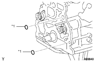
*1 New O-Ring Install 2 new O-rings to the cylinder block sub-assembly.
-
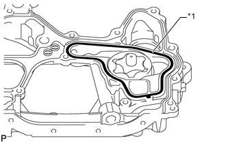
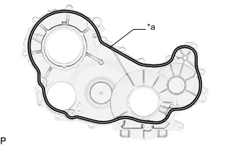
*1 New Gasket Install a new gasket to the groove of the timing gear case assembly.
-
Remove any old seal packing (FIPG material).
-
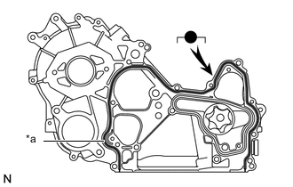
*a Seal Packing Apply seal packing to the timing gear case assembly as shown in the illustration.
Seal packing Toyota Genuine Seal Packing Black, Three Bond 1207B or equivalent Standard seal diameter 4 mm (0.157 in.) Note
After applying seal packing, install the timing gear case assembly within 3 minutes and tighten the bolts within 15 minutes.
-
Align the "2" marks of the No. 1 balanceshaft driven gear and oil pump drive gear.
-
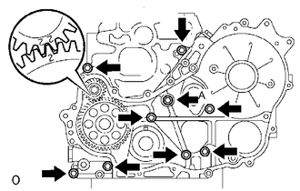
Install the timing gear case assembly to the cylinder block sub-assembly with the union bolt and 8 bolts.
- Torque:
- for union bolt (A)
- 16 N*m { 163 kgf*cm, 12 ft.*lbf }
- for bolt
- 13 N*m { 133 kgf*cm, 10 ft.*lbf }
-
-
INSTALL OIL STRAINER SUB-ASSEMBLY
-
Install a new gasket and the oil strainer sub-assembly with the 2 bolts and 2 nuts.
- Torque:
- 8.0 N*m { 82 kgf*cm, 71 in.*lbf }
-
-
INSTALL OIL PAN SUB-ASSEMBLY
-
Remove any old seal packing (FIPG material).
-
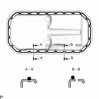
Apply seal packing to the oil pan sub-assembly as shown in the illustration.
Seal packing Toyota Genuine Seal Packing Black, Three Bond 1207B or equivalent Standard seal diameter 4 mm (0.157 in.) Note
After applying seal packing, install the oil pan sub-assembly within 3 minutes and tighten the bolts and nuts within 15 minutes.
-
Install the oil pan sub-assembly to the cylinder block sub-assembly with the 22 bolts and 2 nuts.
- Torque:
- 12 N*m { 122 kgf*cm, 9 ft.*lbf }
-
-
INSTALL INJECTION GEAR
-
Install a new O-ring and the fuel supply pump assembly with the 2 nuts.
- Torque:
- 21 N*m { 214 kgf*cm, 15 ft.*lbf }
-
Temporarily install the injection gear with the nut.
Tech Tips
Fit the key (protrusion) of the fuel supply pump assembly into the key slot of the injection gear.
-
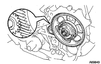
Align the "3" marks of the No. 2 balanceshaft driven gear and injection gear.
-
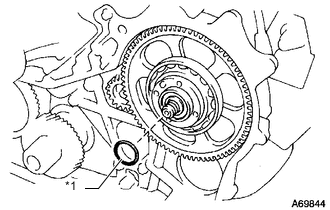
*1 New O-Ring Install a new O-ring to the injection gear.
-
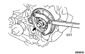
Install the injection gear set nut.
-
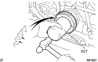
Using SST, tighten the set nut.
- SST
- 09960-10010 ( 09962-01000, 09963-01000 )
- Torque:
- 63.7 N*m { 650 kgf*cm, 47 ft.*lbf }
-
-
INSTALL CRANKSHAFT TIMING GEAR
-
Position the crankshaft timing gear with the "1" timing marks facing forward.
-
Align the key groove of the crankshaft timing gear with the set key on the crankshaft.
-
Using SST and a hammer, tap on the crankshaft timing gear to install it.
- SST
- 09223-00010
-
-
INSTALL NO. 1 IDLE GEAR SHAFT
-
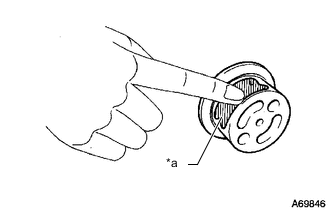
*a Engine Oil Apply a coat of engine oil to the No. 1 idle gear shaft.
-
*a Oil Hole Install the No. 1 idle gear shaft as shown in the illustration.
-
-
INSTALL NO. 2 IDLE SUB GEAR
-
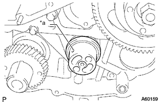
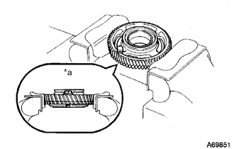
*a Cutout Mark Mount the No. 1 idle gear in a vise.
Note
Be careful not to damage the No. 1 idle gear.
Tech Tips
Make sure the cutout mark of the No. 1 idle gear faces down.
-
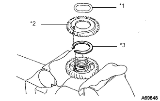
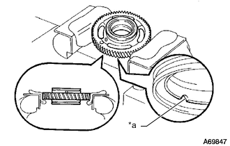
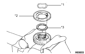
*1 Wave Washer *2 No. 2 Idle Sub Gear *3 Idle Gear Spring Install the idle gear spring.
Tech Tips
Fit the pins on the No. 1 idle gears between the spring ends.
-
Install the No. 2 idle sub gear.
-
Install the wave washer.
-
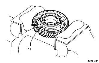
Using snap ring pliers, install the snap ring.
-
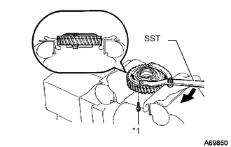
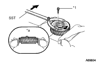
*1 Service Bolt Using SST, align the holes of the No. 1 idle gear and No. 2 idle sub gear by turning the No. 2 idle sub gear clockwise and install a service bolt.
- SST
- 09960-10010 ( 09962-01000, 09963-00700 )
-
Remove the No. 1 idle gear from the vise and turn it upside down.
-
-
INSTALL NO. 1 IDLE SUB GEAR
-
*a Upward Mount the No. 1 idle gear and No. 2 idle sub gear in a vise.
Note
Be careful not to damage the gears.
-
*1 Service Bolt Remove the service bolt.
-
*1 Wave Washer *2 No. 1 Idle Sub Gear *3 Idle Gear Spring Install the idle gear spring.
Tech Tips
Fit the pins on the No. 1 idle gears between the spring ends.
-
Install the No. 1 idle sub gear.
-
Install the wave washer.
-
Using snap ring pliers, install the snap ring.
-
*1 Service Bolt *a Upward Using SST, align the holes of the No. 1 idle gear and No. 1 idle sub gear by turning the No. 1 idle sub gear clockwise, and install a service bolt.
- SST
- 09960-10010 ( 09962-01000, 09963-00600 )
-
-
INSTALL NO. 1 IDLE GEAR
-
*a Turn Align the "4" and "5" timing marks of the No. 1 idle gear and crankshaft timing gear.
-
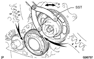
Using SST, turn the injection gear and align the "4" timing marks of the No. 1 idle gear and injection gear, and then mesh the gears.
- SST
- 09960-10010 ( 09962-01000, 09963-00700 )
-
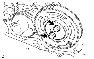
*1 Service Bolt Position the idle gear thrust plate with the protrusion facing forward.
-
Align the bolt holes and install the idle gear thrust plate with the 2 bolts.
- Torque:
- 50 N*m { 510 kgf*cm, 37 ft.*lbf }
-
Remove the service bolt.
-
-
INSTALL NO. 1 CRANKSHAFT POSITION SENSOR PLATE
-
Align the key groove of the No. 1 crankshaft position sensor plate with the set key.
-
Install the No. 1 crankshaft position sensor plate to the crankshaft with the cupped side facing outward.
-
-
INSTALL TIMING GEAR COVER
-
Remove any old seal packing (FIPG material).
-
*a Seal Packing Apply seal packing to the timing gear cover as shown in the illustration.
Seal packing Toyota Genuine Seal Packing Black, Three Bond 1207B or equivalent Standard seal diameter 4 mm (0.157 in.) Note
After applying seal packing, install the timing gear cover within 3 minutes and tighten the bolts within 15 minutes.
-
Install a new O-ring to the timing gear case assembly.
-
Install the timing gear cover to the timing gear case assembly with the 14 bolts and 2 nuts.
- Torque:
- 13 N*m { 133 kgf*cm, 10 ft.*lbf }
-
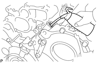
Remove the screw plug and gasket.
-
Pour approximately 50 cc (3.05 cu. in.) of engine oil into the oil pump.
-
Install a new gasket and the screw plug.
- Torque:
- 41.5 N*m { 423 kgf*cm, 31 ft.*lbf }
-
Install the No. 1 vacuum transmitting pipe with the bolt.
- Torque:
- 13 N*m { 133 kgf*cm, 10 ft.*lbf }
-
-
INSTALL ENGINE WATER PUMP ASSEMBLY
-
Install a new gasket and the engine water pump assembly to the cylinder block sub-assembly with the 5 bolts and 2 nuts.
- Torque:
- 13 N*m { 133 kgf*cm, 10 ft.*lbf }
-
-
INSTALL CYLINDER HEAD GASKET
-
INSTALL CYLINDER HEAD SUB-ASSEMBLY
-
INSTALL VALVE LIFTER
-
Install the valve lifters to the cylinder head sub-assembly.
-
Check that each valve lifter rotates smoothly by hand.
-
-
INSTALL CAMSHAFT SUB-ASSEMBLY
-
INSTALL NO. 2 TIMING BELT COVER
-
INSTALL CAMSHAFT TIMING PULLEY
-
INSPECT AND ADJUST VALVE CLEARANCE
-
INSTALL INJECTOR ASSEMBLY
-
INSPECT FOR FUEL LEAK
-
INSTALL CYLINDER HEAD COVER SUB-ASSEMBLY
-
INSTALL OIL FILLER CAP SUB-ASSEMBLY