CYLINDER BLOCK REASSEMBLY

PROCEDURE
-
INSTALL STUD BOLT
Tech Tips
If a stud bolt is deformed or its threads are damaged, replace it.
-
Install the stud bolts to the cylinder block sub-assembly.
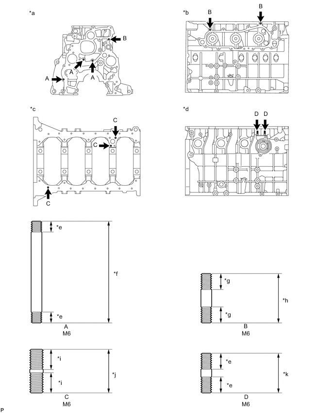
*a Front Side *b Left Side *c Oil Pan Side *d Right Side *e 9 mm (0.354 in.) *f 69 mm (2.72 in.) *g 9.5 mm (0.374 in.) *h 29 mm (1.14 in.) *i 12 mm (0.472 in.) *j 26 mm (1.02 in.) *k 23 mm (0.906 in.) - -
-
-
INSTALL NO. 1 OIL NOZZLE SUB-ASSEMBLY
-
Align the pin of the No. 1 oil nozzle sub-assembly with the pin hole of the cylinder block sub-assembly.
-
Install the 4 No. 1 oil nozzle sub-assemblies with the 4 check valves.
- Torque:
- 26 N*m { 265 kgf*cm, 19 ft.*lbf }
-
-
INSTALL PISTON WITH PIN SUB-ASSEMBLY
-
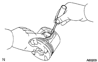
Using a small screwdriver, install a new snap ring on one side of the piston pin hole.
-
Gradually heat the piston to approximately 80°C (176°F).
-
Coat the piston pin with engine oil.
-
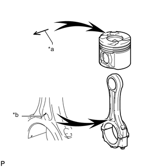
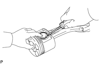
*a Front Mark (Arrow) *b Front Mark (Protrusion) Align the front marks of the piston and connecting rod, connect the connecting rod to the piston, and then push in the piston pin with your thumb.
-
Check the fit between the piston and piston pin. Try to move the piston back and forth on the piston pin.
-
Using a small screwdriver, install a new snap ring on the other side of the piston pin hole.
-
-
INSTALL PISTON RING SET
-
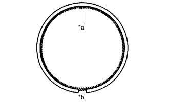
*a Coil Joint *b Oil Ring End Gap Install the coil and oil ring by hand.
Tech Tips
Make sure the end gap of the oil ring and the coil joint are on opposite sides.
-
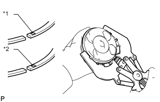
*1 No. 1 Piston Ring *2 No. 2 Piston Ring Using a piston ring expander, install the No. 1 piston ring and No. 2 piston ring with the code mark facing upward.
Code Mark Item Specified Condition No. 1 Piston Ring NAB No. 2 Piston Ring KD1 -
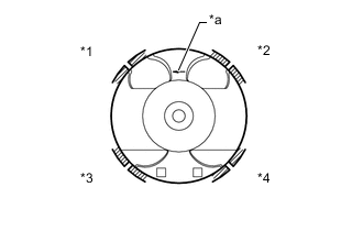
*1 No. 1 Piston Ring *2 Oil Ring *3 Coil *4 No. 2 Piston Ring *a Front Mark (Arrow) Position the piston rings so that the ring ends are as shown in the illustration.
Note
Do not align the ring ends.
-
-
INSTALL CRANKSHAFT BEARING
Tech Tips
Upper crankshaft bearings have an oil groove and oil hole. Lower crankshaft bearings do not.
-
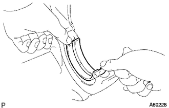
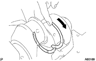
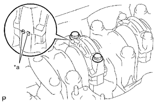
Align the crankshaft bearing claw with the claw groove of the cylinder block sub-assembly and push in the 5 upper crankshaft bearings.
-
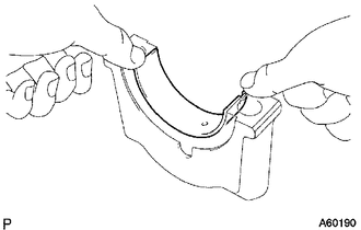
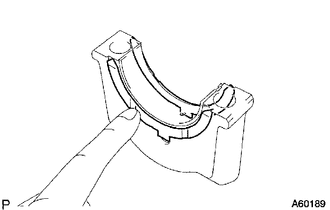
Align the crankshaft bearing claw with the claw groove of the crankshaft bearing cap and push in the 5 lower crankshaft bearings.
-
-
INSTALL CRANKSHAFT
-
Place the crankshaft on the cylinder block sub-assembly.
-
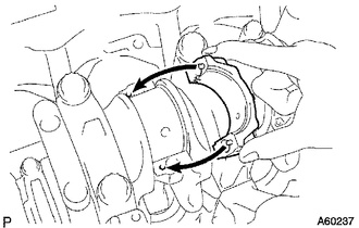
Push the crankshaft in one direction and install one crankshaft thrust washer to the No. 5 journal position with the oil groove facing outward.
-
Push the crankshaft in the opposite direction and install the other crankshaft thrust washer to the No. 5 journal position with the oil groove facing outward.
-
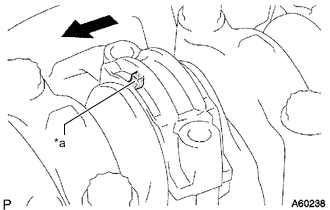
Install the 2 crankshaft thrust washers to the No. 5 bearing cap with the grooves facing outward.
-
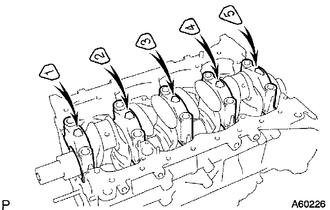
Install the 5 crankshaft bearing caps to their proper locations.
-
Install the crankshaft bearing cap set bolts.
Tech Tips
-
The crankshaft bearing cap set bolts are tightened in 2 progressive steps.
-
If a crankshaft bearing cap set bolt is broken or deformed, replace it.
-
Apply a light coat of engine oil to the threads and under the bolt heads of the crankshaft bearing cap set bolts.
-
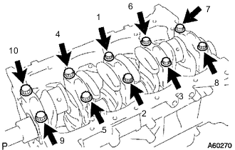
Install and uniformly tighten the 10 crankshaft bearing cap set bolts of the crankshaft bearing caps in several passes in the sequence shown in the illustration.
- Torque:
- 50 N*m { 510 kgf*cm, 37 ft.*lbf }
If any one of the crankshaft bearing cap set bolts does not meet the torque specification, replace the crankshaft bearing cap set bolt.
-
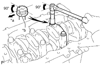
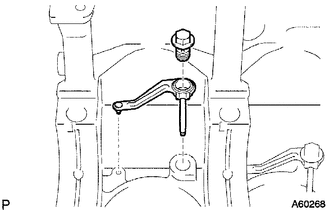
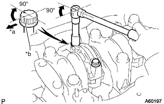
*a Front *b Paint Mark Mark the front of each crankshaft bearing cap bolt with paint.
-
Tighten the crankshaft bearing cap set bolts by 90° in the numerical order shown in the previous illustration.
-
Check that the painted marks are now at a 90° angle to the front.
-
-
Check that the crankshaft turns smoothly.
-
-
INSPECT CRANKSHAFT THRUST CLEARANCE
-
INSTALL CONNECTING ROD BEARING
-
Align the connecting rod bearing claw with the groove of the connecting rod or connecting rod cap.
-
Install the connecting rod bearings to the connecting rod and connecting rod cap.
-
-
INSTALL PISTON AND CONNECTING ROD
-
Apply engine oil to the cylinder walls, the pistons and the surfaces of the connecting rod bearings.
-
Check the positions of the piston ring ends.
-
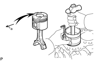
*a Front Mark (Arrow) Using a piston ring compressor, push the correctly numbered piston and connecting rod into the cylinder with the front mark of the piston facing forward.
-
Place the connecting rod cap on the connecting rod.
-
*a Matchmark Match each numbered connecting rod cap with the correct connecting rod.
-
Align the pins of the connecting rod cap with the pin holes of the connecting rod and install the connecting rod cap.
-
*a Front Mark (Protrusion) 
Front Check that the front mark of the connecting rod cap is facing forward.
-
-
Install the connecting rod bolts.
Tech Tips
-
The connecting rod bolts are tightened in 2 progressive steps.
-
If any connecting rod bolt is broken or deformed, replace it.
-
Apply a light coat of engine oil to the threads and under the heads of the connecting rod bolts.
-
Install and alternately tighten the connecting rod bolts of the connecting rod cap in several passes.
- Torque:
- 35 N*m { 357 kgf*cm, 26 ft.*lbf }
Tech Tips
If any one of the connecting rod bolts does not meet the torque specification, replace the connecting rod bolt.
-
*a Front *b Paint Mark Mark the front of each connecting rod bolt with paint.
-
Tighten the connecting rod bolts by 90° as shown in the illustration.
-
Check that the painted marks are now at a 90° angle to the front.
-
-
Check that the crankshaft turns smoothly.
-
-
INSPECT CONNECTING ROD THRUST CLEARANCE
-
INSTALL CYLINDER BLOCK OIL ORIFICE