TIMING BELT INSTALLATION
PROCEDURE
-
INSTALL NO. 1 TIMING BELT IDLER SUB-ASSEMBLY
-
Using a 10 mm hexagon wrench, install a new timing belt idler spacer and the No. 1 timing belt idler sub-assembly to the timing gear cover with the timing belt idler shaft.
- Torque:
- 35 N*m { 357 kgf*cm, 26 ft.*lbf }
-
Check that the No. 1 timing belt idler sub-assembly pulley moves smoothly.
If the No. 1 timing belt idler sub-assembly pulley does not move smoothly, check the installation condition of the No. 1 timing belt idler sub-assembly and timing belt idler spacer.
-
-
INSTALL TIMING BELT
-
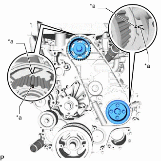
*a Timing Mark Check that the timing marks are aligned as shown in the illustration.
Note
-
Make sure that the engine is cold.
-
When turning the crankshaft pulley, the valve heads will hit against the piston. Do not turn the crankshaft pulley more than necessary.
Tech Tips
If reusing the timing belt, align the points marked during removal, and install the timing belt with the arrow pointing in the direction of crankshaft revolution.
-
-
Install the timing belt to the pump drive shaft pulley, camshaft timing pulley and No. 1 timing belt idler sub-assembly in sequence.
-
Place the timing belt tensioner assembly upright. Then set a press on the top of the timing belt tensioner assembly.
Note
-
Do not scratch or deform the timing belt tensioner assembly rod end.
-
Press in the timing belt tensioner assembly rod.
-
Protect the tip of the timing belt tensioner assembly push rod with a cloth in order to prevent damage.
-
-
Using the press, slowly push in the timing belt tensioner assembly push rod using 981 to 9800 N (100 to 999 kgf, 220 to 2203 lbf) of force.
Note
Do not apply a load of over 9800 N (999 kgf, 2203 lbf) to the timing belt tensioner assembly push rod.
-
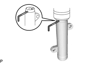
Align the holes of the timing belt tensioner assembly push rod and housing. Then pass a 1.5 mm hexagon wrench through the holes to fix the timing belt tensioner assembly push rod in place.
-
Temporarily install the timing belt tensioner assembly to the timing gear cover with the 2 bolts while pushing the No. 1 timing belt idler sub-assembly pulley toward the timing belt.
-
Tighten the 2 bolts.
- Torque:
- 13 N*m { 133 kgf*cm, 10 ft.*lbf }
Note
Uniformly tighten the 2 bolts.
-
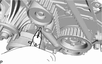
Remove the 1.5 mm hexagon wrench from the timing belt tensioner assembly.
-
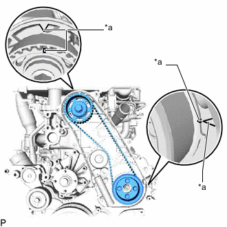
*a Timing Mark Turn the crankshaft clockwise 720° and check that the timing marks are aligned as shown in the illustration.
-
-
INSTALL NO. 1 TIMING BELT COVER
-
Install the No. 1 timing belt cover and 6 washers to the No. 2 timing belt cover and timing gear cover with the 6 bolts.
- Torque:
- 6.0 N*m { 61 kgf*cm, 53 in.*lbf }
-
-
INSTALL FAN SHROUD
-
INSTALL NO. 1 RADIATOR HOSE
-
ADD ENGINE COOLANT
-
INSPECT FOR COOLANT LEAK
-
INSTALL NO. 1 ENGINE UNDER COVER ASSEMBLY