ECD SYSTEM(w/ DPF) VC Output Circuit
DESCRIPTION
The ECM constantly generates a 5 V power source voltage from the battery voltage supplied to the +B (BATT) terminal to operate the microprocessor. The ECM also provides this power source voltage to the sensors through the VC output circuit.
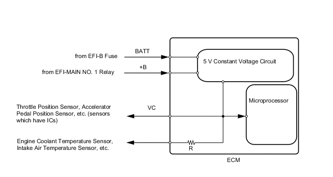
When the VC circuit has a short circuit, the CPU in the ECM and sensors that are supplied power through the VC circuit are deactivated because power is not supplied from the VC circuit. When the system is in this condition, it will not start.
WIRING DIAGRAM
-
For the circuit diagram of the ECM power source circuit.
-
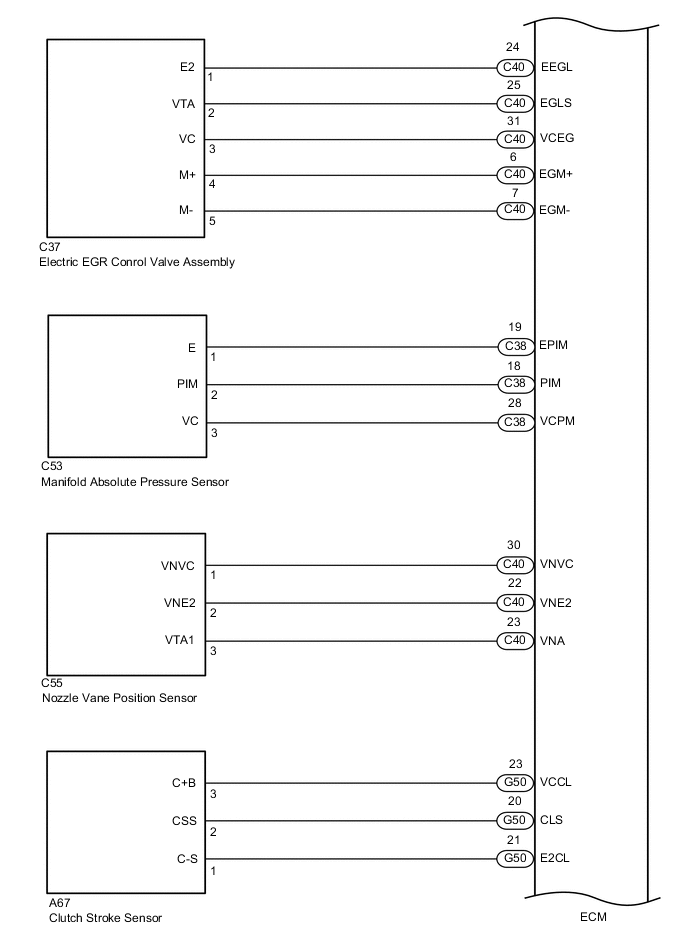
VC Power Source Circuit
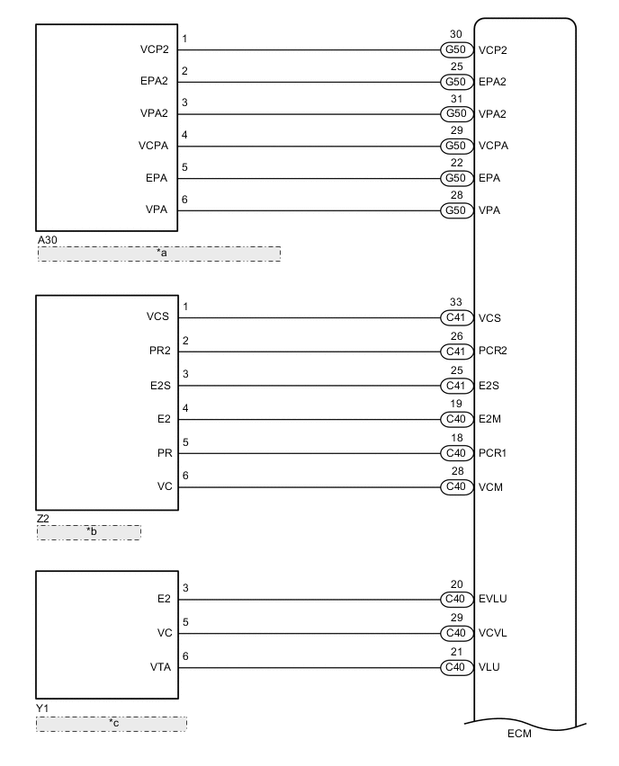
| *a | Accelerator Pedal Position Sensor (Accelerator Pedal Sensor Assembly) |
| *b | Fuel Pressure Sensor |
| *c | Diesel Throttle Body Assembly |
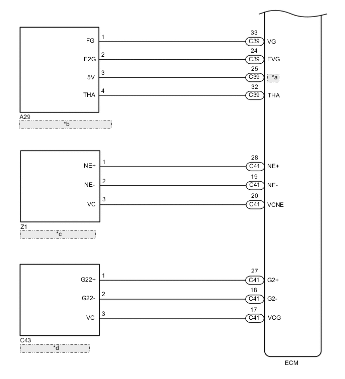
| *a | VCVG |
| *b | Mass Air Flow Meter Sub-assembly |
| *c | Crankshaft Position Sensor |
| *d | Camshaft Position Sensor |
CAUTION / NOTICE / HINT
Note
-
Check the fuses for circuits related to this system before performing the following inspection procedure.
-
After replacing the ECM, the new ECM needs registration (Click here ) and initialization Click here.
PROCEDURE
-
CHECK CONNECTION BETWEEN GTS AND ECM
-
Connect the GTS to the DLC3.
-
Turn the ignition switch to ON.
-
Turn the GTS on.
-
Check the communication between the GTS and ECM.
Tech Tips
It can be checked using the "Engine" item of the Data List.
Result Result Proceed to Communication is not possible A Communication is possible B
B 
PROCEED TO NEXT SUSPECTED AREA SHOWN IN PROBLEM SYMPTOMS TABLE Click here
A 
-
-
CHECK TERMINAL VOLTAGE (POWER SOURCE OF ECM)
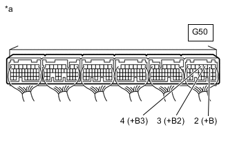
*a Component with harness connected
(to ECM)
-
Turn the ignition switch to ON.
-
Measure the voltage according to the value(s) in the table below.
Standard Voltage Tester Connection Condition Specified Condition G50-2 (+B) - Body ground Ignition switch ON 11 to 14 V G50-3 (+B2) - Body ground Ignition switch ON 11 to 14 V G50-4 (+B3) - Body ground Ignition switch ON 11 to 14 V Tech Tips
If the result is not as specified, since current is not flowing to the +B, +B2 and +B3 terminals of the ECM, the system may not be started.
Result Proceed to OK NG
NG
GO TO ECM POWER SOURCE CIRCUIT Click here
OK
-
-
CHECK CONNECTION BETWEEN GTS AND ECM (CAMSHAFT POSITION SENSOR)
-
Disconnect the camshaft position sensor connector.
-
Turn the ignition switch to ON.
-
Turn the GTS on.
-
Check the communication between the GTS and ECM.
Tech Tips
It can be checked using the "Engine" item of the Data List.
Result Result Proceed to Communication is possible A Communication is not possible B -
Reconnect the camshaft position sensor connector.
A
REPLACE CAMSHAFT POSITION SENSOR Click here
B
-
-
CHECK CONNECTION BETWEEN GTS AND ECM (MANIFOLD ABSOLUTE PRESSURE SENSOR)
-
Disconnect the manifold absolute pressure sensor connector.
-
Turn the ignition switch to ON.
-
Turn the GTS on.
-
Check the communication between the GTS and ECM.
Tech Tips
It can be checked using the "Engine" item of the Data List.
Result Result Proceed to Communication is possible A Communication is not possible B -
Reconnect the manifold absolute pressure sensor connector.
A
REPLACE MANIFOLD ABSOLUTE PRESSURE SENSOR Click here
B
-
-
CHECK CONNECTION BETWEEN GTS AND ECM (MASS AIR FLOW METER SUB-ASSEMBLY)
-
Disconnect the mass air flow meter sub-assembly connector.
-
Turn the ignition switch to ON.
-
Turn the GTS on.
-
Check the communication between the GTS and ECM.
Tech Tips
It can be checked using the "Engine" item of the Data List.
Result Result Proceed to Communication is possible A Communication is not possible B -
Reconnect the mass air flow meter sub-assembly connector.
A
REPLACE MASS AIR FLOW METER SUB-ASSEMBLY Click here
B
-
-
CHECK CONNECTION BETWEEN GTS AND ECM (NOZZLE VANE POSITION SENSOR)
-
Disconnect the nozzle vane position sensor connector.
-
Turn the ignition switch to ON.
-
Turn the GTS on.
-
Check the communication between the GTS and ECM.
Tech Tips
It can be checked using the "Engine" item of the Data List.
Result Result Proceed to Communication is possible A Communication is not possible B -
Reconnect the nozzle vane position sensor connector.
A
REPLACE TURBOCHARGER NOZZLE VANE CONTROL ACTUATOR Click here
B
-
-
CHECK CONNECTION BETWEEN GTS AND ECM (ELECTRIC EGR CONTROL VALVE ASSEMBLY)
-
Disconnect the electric EGR control valve assembly connector.
-
Turn the ignition switch to ON.
-
Turn the GTS on.
-
Check the communication between the GTS and ECM.
Tech Tips
It can be checked using the "Engine" item of the Data List.
Result Result Proceed to Communication is possible A Communication is not possible B -
Reconnect the electric EGR control valve assembly connector.
A
REPLACE ELECTRIC EGR CONTROL VALVE ASSEMBLY Click here
B
-
-
CHECK CONNECTION BETWEEN GTS AND ECM (ACCELERATOR PEDAL POSITION SENSOR)
-
Disconnect the accelerator pedal position sensor connector.
-
Turn the ignition switch to ON.
-
Turn the GTS on.
-
Check the communication between the GTS and ECM.
Tech Tips
It can be checked using the "Engine" item of the Data List.
Result Result Proceed to Communication is possible A Communication is not possible B -
Reconnect the accelerator pedal position sensor connector.
A
REPLACE ACCELERATOR PEDAL SENSOR ASSEMBLY Click here
B
-
-
CHECK CONNECTION BETWEEN GTS AND ECM (FUEL PRESSURE SENSOR)
-
Disconnect the fuel pressure sensor connector.
-
Turn the ignition switch to ON.
-
Turn the GTS on.
-
Check the communication between the GTS and ECM.
Tech Tips
It can be checked using the "Engine" item of the Data List.
Result Result Proceed to Communication is possible A Communication is not possible B -
Reconnect the fuel pressure sensor connector.
A
REPLACE COMMON RAIL ASSEMBLY Click here
B
-
-
CHECK CONNECTION BETWEEN GTS AND ECM (DIESEL THROTTLE BODY ASSEMBLY)
-
Disconnect the diesel throttle body assembly connector.
-
Turn the ignition switch to ON.
-
Turn the GTS on.
-
Check the communication between the GTS and ECM.
Tech Tips
It can be checked using the "Engine" item of the Data List.
Result Result Proceed to Communication is possible A Communication is not possible B -
Reconnect the diesel throttle body assembly connector.
A
REPLACE DIESEL THROTTLE BODY ASSEMBLY Click here
B
-
-
CHECK CONNECTION BETWEEN GTS AND ECM (CRANKSHAFT POSITION SENSOR)
-
Disconnect the crankshaft position sensor connector.
-
Turn the ignition switch to ON.
-
Turn the GTS on.
-
Check the communication between the GTS and ECM.
Tech Tips
It can be checked using the "Engine" item of the Data List.
Result Result Proceed to Communication is possible A Communication is not possible B -
Reconnect the crankshaft position sensor connector.
A
REPLACE CRANKSHAFT POSITION SENSOR Click here
B
-
-
CHECK CONNECTION BETWEEN GTS AND ECM (CLUTCH STROKE SENSOR)
-
Disconnect the clutch stroke sensor connector.
-
Turn the ignition switch to ON.
-
Turn the GTS on.
-
Check the communication between the GTS and ECM.
Tech Tips
It can be checked using the "Engine" item of the Data List.
Result Result Proceed to Communication is possible A Communication is notpossible B -
Reconnect the clutch stroke sensor connector.
A
REPLACE MASTER CYLINDER ASSEMBLY
B
-
-
CHECK HARNESS AND CONNECTOR
-
Disconnect the camshaft position sensor connector.
-
Disconnect the manifold absolute pressure sensor connector.
-
Disconnect the mass air flow meter sub-assembly connector.
-
Disconnect the nozzle vane position sensor connector.
-
Disconnect the electric EGR control valve assembly connector.
-
Disconnect the accelerator pedal sensor assembly connector.
-
Disconnect the fuel pressure sensor connector.
-
Disconnect the diesel throttle body assembly connector.
-
Disconnect the crankshaft position sensor connector.
-
Disconnect the clutch stroke sensor connector.
-
Disconnect the ECM connectors.
-
Measure the resistance according to the value(s) in the table below.
Standard Resistance Tester Connection Condition Specified Condition G50-29 (VCPA) - Body ground and other terminals Always 10 kΩ or higher G50-30 (VCP2) - Body ground and other terminals Always 10 kΩ or higher C40-28 (VCM) - Body ground and other terminals Always 10 kΩ or higher C41-33 (VCS) - Body ground and other terminals Always 10 kΩ or higher C40-29 (VCVL) - Body ground and other terminals Always 10 kΩ or higher C40-31 (VCEG) - Body ground and other terminals Always 10 kΩ or higher C38-28 (VCPM) - Body ground and other terminals Always 10 kΩ or higher C40-30 (VNVC) - Body ground and other terminals Always 10 kΩ or higher C39-25 (VCVG) - Body ground and other terminals Always 10 kΩ or higher C41-17 (VCG) - Body ground and other terminals Always 10 kΩ or higher C41-20 (VCNE) - Body ground and other terminals Always 10 kΩ or higher G50-23 (VCCL) - Body ground and other terminals Always 10 kΩ or higher -
Reconnect the clutch stroke sensor connector.
-
Reconnect the crankshaft position sensor connector.
-
Reconnect the diesel throttle body assembly connector.
-
Reconnect the fuel pressure sensor connector.
-
Reconnect the accelerator pedal sensor assembly connector.
-
Reconnect the electric EGR control valve assembly connector.
-
Reconnect the nozzle vane position sensor connector.
-
Reconnect the mass air flow meter sub-assembly connector.
-
Reconnect the manifold absolute pressure sensor connector.
-
Reconnect the camshaft position sensor connector.
-
Reconnect the ECM connectors.
Result Proceed to OK NG
OK
REPLACE ECM Click here
NG
REPAIR OR REPLACE HARNESS OR CONNECTOR
-