ECD SYSTEM(w/ DPF), Diagnostic DTC:P0545, P0546
| DTC Code | DTC Name |
|---|---|
| P0545 | Exhaust Gas Temperature Sensor Circuit Low (Bank 1 Sensor 1) |
| P0546 | Exhaust Gas Temperature Sensor Circuit High (Bank 1 Sensor 1) |
DESCRIPTION
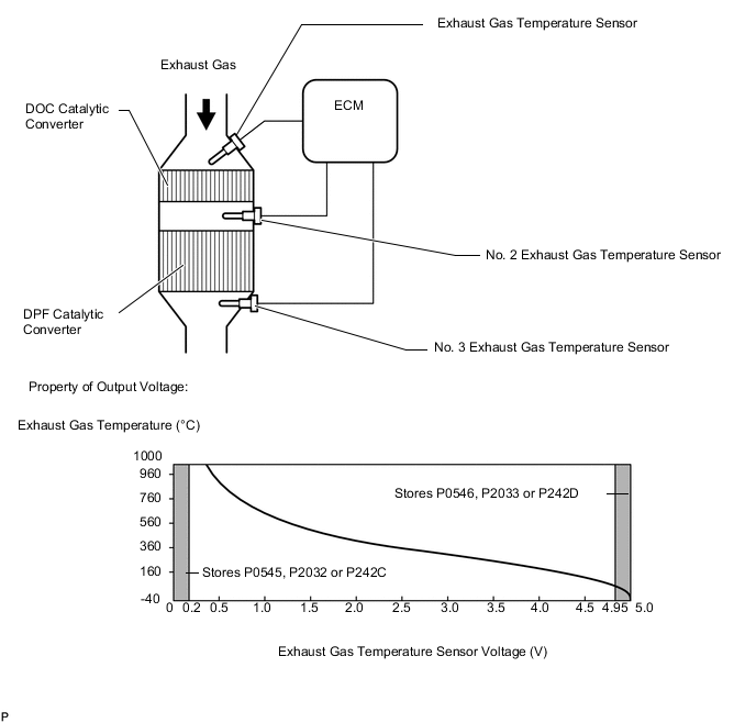
The exhaust gas temperature sensors are installed before and after the exhaust manifold converter sub-assembly to sense the exhaust gas temperature.
A thermistor built into the sensor changes its resistance value according to the exhaust gas temperature. The lower the exhaust gas temperature, the higher the thermistor resistance value. The higher the exhaust gas temperature, the lower the thermistor resistance value.
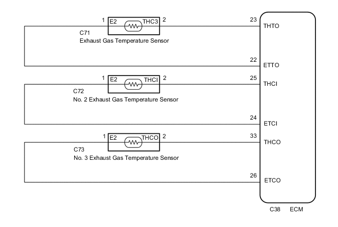
The exhaust gas temperature sensor is powered by a 5 V supply from the THTO (B1S1), THCI (B1S2) and THCO (B1S3) terminals of the ECM, via resistor R.
Resistor R and the exhaust gas temperature sensor are connected in series. When the resistance value of the exhaust gas temperature sensor changes in accordance with the exhaust gas temperature, the voltage at terminals THTO (B1S1), THCI (B1S2) and THCO (B1S3) also changes. The No. 1 exhaust gas temperature sensor monitors the temperature upstream of the DOC catalyst. The No. 2 exhaust gas temperature sensor monitors the temperature upstream of the DPF catalyst. The No. 3 exhaust gas temperature sensor monitors the rise in temperature of the DPF catalyst. When PM forced regeneration is needed, the ECM operates the exhaust fuel addition injector assembly to obtain target upstream temperature of the DPF catalytic converter as monitored through sensor 2. In addition, the ECM monitors the temperature increase of the exhaust manifold converter sub-assembly using sensor 3.
| DTC No. | Detection Item | DTC Detection Condition | Trouble Area | MIL | Memory |
|---|---|---|---|---|---|
| P0545 | Exhaust Gas Temperature Sensor Circuit Low (Bank 1 Sensor 1) | Exhaust gas temperature sensor output voltage is below 0.2 V for 3 seconds or more when all conditions are met. (1 trip detection logic):
|
|
Comes on | DTC stored |
| P0546 | Exhaust Gas Temperature Sensor Circuit High (Bank 1 Sensor 1) | Exhaust gas temperature sensor output voltage is higher than 4.95 V for 3 seconds or more when all conditions are met. (1 trip detection logic):
|
|
Comes on | DTC stored |
| DTC No. | Data List |
|---|---|
| P0545 | Exhaust Temperature B1S1 |
| P0546 |
Tech Tips
-
DTC P20CF (Exhaust fuel addition injector assembly malfunction) may be stored if there is an open malfunction in an exhaust gas temperature sensor circuit.
-
Sensor 1 represents the sensor located upstream of the DOC catalytic converter.
-
When DTC P0545 and P0546 is output, check the exhaust gas temperature indicated by "Powertrain / Engine and ECT / Data List / Diesel Exhaust / Exhaust Temperature B1S1" using the GTS.
| Condition | Exhaust Temperature B1S1 | Exhaust Gas Temperature Sensor Condition |
|---|---|---|
| Idling with warm engine | Constant at between 50 and 700°C (122 and 1292°F) | Normal |
| 0°C (32°F) | Open circuit | |
| 1000°C (1832°F) | Short circuit |
MONITOR DESCRIPTION
The ECM constantly monitors the output voltages from the exhaust gas temperature sensors in order to detect problems with the sensors. When the sensor output voltage deviates from the normal operating range (between 0.2 V and 4.95 V) for more than 3 seconds after the engine is warmed up, the ECM interprets this as malfunction of the sensor circuit and illuminates the MIL.
CONFIRMATION DRIVING PATTERN
| DTC No. | DTC Detection Drive Pattern |
|---|---|
| P0545 | Idle the engine for 3 seconds after warming up the engine (the engine coolant temperature is 60°C (140°F) or higher) and allowing 11 minutes to elapse after starting the engine. |
| P0546 |
WIRING DIAGRAM
CAUTION / NOTICE / HINT
Note
After replacing the ECM, the new ECM needs registration (Click here) and initialization Click here.
Tech Tips
Read freeze frame data using the GTS. Freeze frame data records the engine condition when malfunctions are detected. When troubleshooting, freeze frame data can help determine if the vehicle was moving or stationary, if the engine was warmed up or not, and other data from the time the malfunction occurred.
PROCEDURE
-
READ VALUE USING GTS (EXHAUST TEMPERATURE)
-
Connect the GTS to the DLC3.
-
Turn the ignition switch to ON and turn the GTS on.
-
Enter the following menus: Powertrain / Engine and ECT / Data List / Diesel Exhaust / Exhaust Temperature B1S1
Powertrain > Engine > Data ListTester Display Exhaust Temperature B1S1 -
Read the value.
Standard Same as the actual exhaust gas temperature (50 to 700°C [122 to 1292°F] during idling with warm engine), and varies after an engine speed of 3000 rpm is maintained for 1 minute. Result Temperature Displayed Proceed to 0°C (32°F) (After warming up the engine) A 1000°C (1832°F) B Same as the actual exhaust gas temperature C Tech Tips
-
If there is a short circuit, the GTS will indicate 0°C (32°F).
-
If there is an open circuit, the GTS will indicate 1000°C (1832°F).
-
B 
READ VALUE USING GTS (CHECK FOR SHORT IN WIRE HARNESS) Click here
C
GO TO STEP 11 Click here
A 
-
-
READ VALUE USING GTS (CHECK FOR OPEN IN WIRE HARNESS)
-
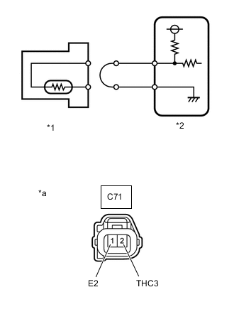
*1 Exhaust Gas Temperature Sensor *2 ECM *a Front view of wire harness connector
(to Exhaust Gas Temperature Sensor)
Disconnect the exhaust gas temperature sensor connector.
-
Connect terminals 1 and 2 of the exhaust gas temperature sensor connector on the wire harness side.
-
Connect the GTS to the DLC3.
-
Turn the ignition switch to ON and turn the GTS on.
-
Enter the following menus: Powertrain / Engine and ECT / Data List / Diesel Exhaust / Exhaust Temperature B1S1.
Powertrain > Engine > Data ListTester Display Exhaust Temperature B1S1 -
Read the value.
Standard 1000°C (1832°F) Result Proceed to OK NG
NG
CHECK HARNESS AND CONNECTOR (EXHAUST GAS TEMPERATURE SENSOR - ECM) Click here
OK
-
-
REPLACE EXHAUST GAS TEMPERATURE SENSOR
-
Replace the exhaust gas temperature sensor.
Result Proceed to NEXT
NEXT
GO TO STEP 11 Click here
-
-
CHECK HARNESS AND CONNECTOR (EXHAUST GAS TEMPERATURE SENSOR - ECM)
-
Disconnect the exhaust gas temperature sensor connector.
-
Disconnect the ECM connector.
-
Measure the resistance according to the value(s) in the table below.
Standard Resistance Tester Connection Condition Specified Condition C71-2(THC3) - C38-23 (THTO) Always Below 1 Ω C71-1(E2) - C38-22 (ETTO) Always Below 1 Ω Result Proceed to OK NG
NG
GO TO STEP 10 Click here
OK
-
-
REPLACE ECM
-
Replace the ECM.
Result Proceed to NEXT
NEXT
GO TO STEP 11 Click here
-
-
READ VALUE USING GTS (CHECK FOR SHORT IN WIRE HARNESS)
-
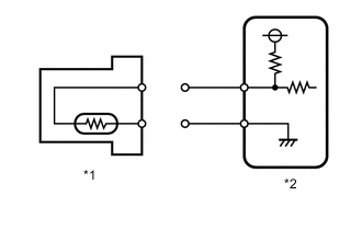
*1 Exhaust Gas Temperature Sensor *2 ECM Disconnect the exhaust gas temperature sensor connector.
-
Connect the GTS to the DLC3.
-
Turn the ignition switch to ON and turn the GTS on.
-
Enter the following menus: Powertrain / Engine and ECT / Data List / Diesel Exhaust / Exhaust Temperature B1S1.
Powertrain > Engine > Data ListTester Display Exhaust Temperature B1S1 -
Read the value.
Standard 0°C (32°F) Result Proceed to OK NG
NG
CHECK HARNESS AND CONNECTOR (EXHAUST GAS TEMPERATURE SENSOR - ECM) Click here
OK
-
-
REPLACE EXHAUST GAS TEMPERATURE SENSOR
-
Replace the exhaust gas temperature sensor.
Result Proceed to NEXT
NEXT
GO TO STEP 11 Click here
-
-
CHECK HARNESS AND CONNECTOR (EXHAUST GAS TEMPERATURE SENSOR - ECM)
-
Disconnect the exhaust gas temperature sensor connector.
-
Disconnect the ECM connector.
-
Measure the resistance according to the value(s) in the table below.
Standard Resistance Tester Connection Condition Specified Condition C71-2(THC3) or C38-23 (THTO) - Body ground and other terminals Always 10 kΩ or higher Result Proceed to OK NG
NG
REPAIR OR REPLACE HARNESS OR CONNECTOR Click here
OK
-
-
REPLACE ECM
-
Replace the ECM.
Result Proceed to NEXT
NEXT
GO TO STEP 11 Click here
-
-
REPAIR OR REPLACE HARNESS OR CONNECTOR
-
Repair or replace the harness or connector.
Result Proceed to NEXT
NEXT
-
-
CONFIRM WHETHER MALFUNCTION HAS BEEN SUCCESSFULLY REPAIRED
-
Connect the GTS to the DLC3.
-
Turn the ignition switch to ON.
-
Turn the GTS on.
-
Clear the DTCs.
Powertrain > Engine > Clear DTCs -
Turn the ignition switch off for 30 seconds or more.
-
Start the engine and turn the GTS on.
-
Idle the engine for 3 seconds or more after warming up the engine (the engine coolant temperature is 60°C (140°F) or higher) and allowing 6 minutes to elapse after starting the engine.
-
Enter the following menus: Powertrain / Engine and ECT / Trouble Codes.
Powertrain > Engine > Trouble Codes -
Confirm that the DTC is not output.
Result Proceed to NEXT
NEXT 
END
-