ECD SYSTEM, Diagnostic DTC:P2009, P2010
| DTC Code | DTC Name |
|---|---|
| P2009 | Intake Manifold Runner Control Circuit Low (Bank 1) |
| P2010 | Intake Manifold Runner Control Circuit High (Bank 1) |
DESCRIPTION
Refer to DTC P2006 Click here.
| DTC No. | Detection Item | DTC Detection Condition | Trouble Area | MIL | Memory |
|---|---|---|---|---|---|
| P2009 | Intake Manifold Runner Control Circuit Low (Bank 1) | Open in vacuum switching valve (for swirl control valve) circuit for 0.5 seconds (2 trip detection logic). |
|
Comes on | DTC stored |
| P2010 | Intake Manifold Runner Control Circuit High (Bank 1) | Short in vacuum switching valve (for swirl control valve) circuit for 0.5 seconds (2 trip detection logic). |
|
Comes on | DTC stored |
CONFIRMATION DRIVING PATTERN
| DTC Detection Drive Pattern | 2 seconds after engine is started, race engine for 1 second |
WIRING DIAGRAM
Refer to DTC P2006 Click here.
CAUTION / NOTICE / HINT
Note
After replacing the ECM, the new ECM needs registration (See page ) and initialization Click here.
Tech Tips
Read freeze frame data using the GTS. Freeze frame data records the engine condition when a malfunction is detected. When troubleshooting, freeze frame data can help determine if the vehicle was moving or stationary, if the engine was warmed up or not, and other data from the time the malfunction occurred.
PROCEDURE
-
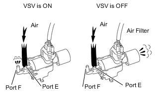
PERFORM ACTIVE TEST USING GTS (ACTIVATE THE VSV FOR SWIRL CONTROL VALVE)
-
Connect the GTS to the DLC3.
-
Disconnect the vacuum hoses from the vacuum switching valve (for Swirl Control Valve).
-
Turn the ignition switch to ON and turn the GTS on.
-
Enter the following menus: Powertrain / Engine / Active Test / Activate the VSV for Swirl Control Valve.
Powertrain > Engine > Active TestTester Display Activate the VSV for Swirl Control Valve -
Check the VSV operation when it is operated using the GTS.
OK GTS Operation Specified Condition VSV ON Air from port E flows out through port F VSV OFF Air from port E flows out through air filter -
Reconnect the vacuum hoses.
Result Proceed to OK NG
OK 
CHECK FOR INTERMITTENT PROBLEMS Click here
NG 
-
-
INSPECT VACUUM SWITCHING VALVE FOR SWIRL CONTROL VALVE (RESISTANCE)
-
Inspect the vacuum switching valve (for swirl control valve).
Result Proceed to OK NG
NG 
REPLACE VACUUM SWITCHING VALVE (FOR SWIRL CONTROL VALVE) Click here
OK
-
-
INSPECT VACUUM SWITCHING VALVE (FOR SWIRL CONTROL VALVE) (POWER SOURCE VOLTAGE)
-
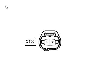
*a Front view of wire harness connector
(to Vacuum Switching Valve [for Swirl Control Valve])
Disconnect the vacuum switching valve (for swirl control valve) connector.
-
Measure the voltage according to the value(s) in the table below.
Standard Voltage Tester Connection Switch Condition Specified Condition C130-2 - Body ground Ignition switch ON 11 to 14 V Result Proceed to OK NG
NG
CHECK HARNESS AND CONNECTOR (VACUUM SWITCHING VALVE [FOR SWIRL CONTROL VALVE] - INSTRUMENT PANEL JUNCTION BLOCK) Click here
OK
-
-
CHECK HARNESS AND CONNECTOR (VACUUM SWITCHING VALVE [FOR SWIRL CONTROL VALVE] - ECM)
-
Disconnect the vacuum switching valve (for swirl control valve) connector.
-
Disconnect the ECM connector.
-
Measure the resistance according to the value(s) in the table below.
Standard Resistance Tester Connection Condition Specified Condition C130-1 - C114-15 (SCV) Always Below 1 Ω C130-1 or C114-15 (SCV) - Body ground Always 10 kΩ or higher -
Reconnect the vacuum switching valve (for swirl control valve) connector.
-
Reconnect the ECM connector.
Result Proceed to OK NG
NG
GO TO STEP 9 Click here
OK
-
-
REPLACE ECM
-
Replace the ECM.
Result Proceed to NEXT
NEXT
GO TO STEP 10 Click here
-
-
REPLACE VACUUM SWITCHING VALVE (FOR SWIRL CONTROL VALVE)
-
Replace the vacuum switching valve (for swirl control valve).
Result Proceed to NEXT
NEXT
GO TO STEP 10 Click here
-
-
CHECK HARNESS AND CONNECTOR (VACUUM SWITCHING VALVE [FOR SWIRL CONTROL VALVE] - INSTRUMENT PANEL JUNCTION BLOCK)
-
Disconnect the instrument panel junction block connector.
-
Disconnect the vacuum switching valve (for swirl control valve) connector.
-
Measure the resistance according to the value(s) in the table below.
Standard Resistance Tester Connection Condition Specified Condition 2N-1 - C130-2 Always Below 1 Ω 2N-1 or C130-2 - Body ground Always 10 kΩ or higher -
Reconnect the instrument panel junction block connector.
-
Reconnect the vacuum switching valve (for swirl control valve) connector.
Result Proceed to OK NG
NG
REPAIR OR REPLACE HARNESS OR CONNECTOR Click here
OK
-
-
INSPECT ECM POWER SOURCE CIRCUIT
-
Check the ECM power source circuit.
Result Proceed to NEXT
NEXT
GO TO STEP 10 Click here
-
-
REPAIR OR REPLACE HARNESS OR CONNECTOR
-
Repair or replace harness or connector.
Result Proceed to NEXT
NEXT
-
-
CONFIRM WHETHER MALFUNCTION HAS BEEN SUCCESSFULLY REPAIRED
-
Connect the GTS to the DLC3.
-
Clear the DTCs.
Powertrain > Engine > Clear DTCs -
Start the engine and wait for 3 seconds or more.
-
Enter the following menus: Powertrain / Engine / Trouble Codes.
Powertrain > Engine > Trouble Codes -
Confirm that the DTC is not output again.
Result Proceed to NEXT
NEXT
END
-