CRANKSHAFT POSITION SENSOR REMOVAL
CAUTION / NOTICE / HINT
The necessary procedures (adjustment, calibration, initialization, or registration) that must be performed after parts are removed, installed, or replaced during the crankshaft position sensor removal/installation are shown below.
| Replacement Part or Procedure | Necessary Procedures | Effects/Inoperative when not Performed | Link |
|---|---|---|---|
| Replacement of ECM |
|
|
|
for RC61F: |
|
||
| Code registration (Immobiliser system) | Engine start function | See the Service Bulletin for the registration method. | |
| Replacement of engine assembly |
|
Engine starting | |
| Clear Crank Time Compensation Data | Engine starting | ||
for AC60F: |
Reset memory |
|
|
for AC60F: |
ATF thermal degradation estimate reset | The value of the Data List item "ATF Thermal Degradation Estimate" is not estimated correctly | |
w/ Automatic Headlight Beam Level Control System: |
Headlight leveling ECU assembly initialization | Headlight leveling function | |
| Front wheel alignment adjustment |
|
VSC malfunctioning |
PROCEDURE
-
REMOVE AUTOMATIC TRANSMISSION ASSEMBLY (for Automatic Transmission)
-
REMOVE MANUAL TRANSMISSION ASSEMBLY (for Manual Transmission)
-
REMOVE CLUTCH COVER ASSEMBLY (for Manual Transmission)
-
REMOVE CLUTCH DISC ASSEMBLY (for Manual Transmission)
-
REMOVE FLYWHEEL SUB-ASSEMBLY
-
REMOVE REAR END PLATE
-
REMOVE NO. 1 CYLINDER BLOCK INSULATOR
-
REMOVE NO. 5 CYLINDER BLOCK INSULATOR
-
REMOVE CONNECTING WIRE
-
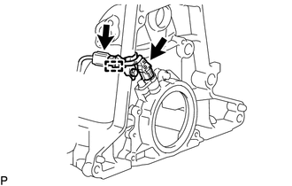
Disconnect the 2 connectors and clamp and remove the connecting wire.
-
-
REMOVE CRANKSHAFT POSITION SENSOR HARNESS BRACKET
-
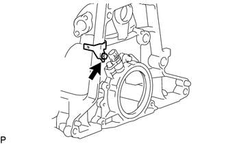
Remove the bolt and crankshaft position sensor harness bracket from the cylinder block sub-assembly.
-
-
REMOVE CRANKSHAFT POSITION SENSOR
-
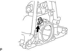
Remove the bolt and crankshaft position sensor from the rear oil seal retainer.
-